STEPS
For Fence-Antenna Leg:
1. Screw (1) glide (B) into each
leg (A) to be installed.
2. Determine the location of the legs per
the plan. Refer to stability guideline
pages in the Antenna Price List/ Planning
Guide, under "Fence Structure".
3. Attach the legs to the underside of
the Fence frames with (4) ¼-20 x 1 ¼"
self tapping screws (C) per leg.
NOTE: Legs attach (at minimum) 12" in
from the end of the Fence frames.
For Fence-Antenna Stabilizer Foot:
4. Determine the locations of the legs
requiring stabilizer feet per the plan.
NOTE: Not all legs require stabilizer feet. Refer
to stability guideline pages in the Antenna Price
List/ Planning Guide, under "Fence Structure".
5. For each leg requiring a stabilizer foot,
slide (1)
5
/
16
–18 weld nut (D) into the
slot on the side of the leg. The nut will
slide into the leg from the bottom.
6. Position a stabilizer foot (E) against the side
of leg (A) with the weld nut (D). The glide
(B) will sit on top of the stabilizer foot (E).
7. Attach the stabilizer foot loosely to the weld nut
(D) with (1)
5
/
16
– 18 x ¾" machine screw (F).
8. Attach and level the Fence frames per the plan.
9. Tighten all of the screws (F) in the stabilizer
feet (E) and adjust the leg glides (B) so they
are snug against the stabilizer feet (E).
Fence-Antenna Leg & Stabilizer Foot
Pattern Numbers Represented:
Individual Legs, YFL_
Stabilizer Foot, YFLSF
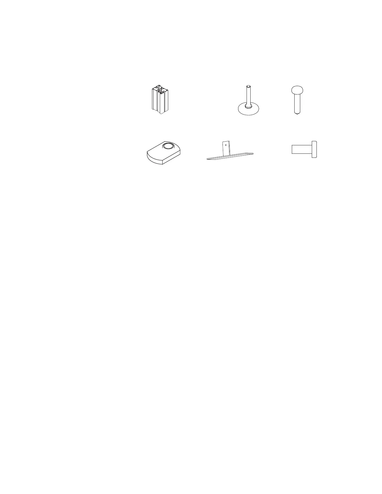
Parts List:
Leg (A)
Glide (B)
¼-20 x 1 ¼" Self Tapping Screw (C)
5
/
16
– 18 Weld Nut (D)
Stabilizer Foot (E)
5
/
16
– 18 x ¾" Machine Screw (F)
Fence Frame
Tools Needed:
Drill
Phillips #2 and #3 bits
(A) 3AB103503* (3.080" for 25"H Fence)
3AB103504* (6.375" for 28"H Fence)
(B) 1C5948352 (C) 6AA412296
(D) 7485400 (E) 3AB1190 (black only) (F) 7060440
Fence