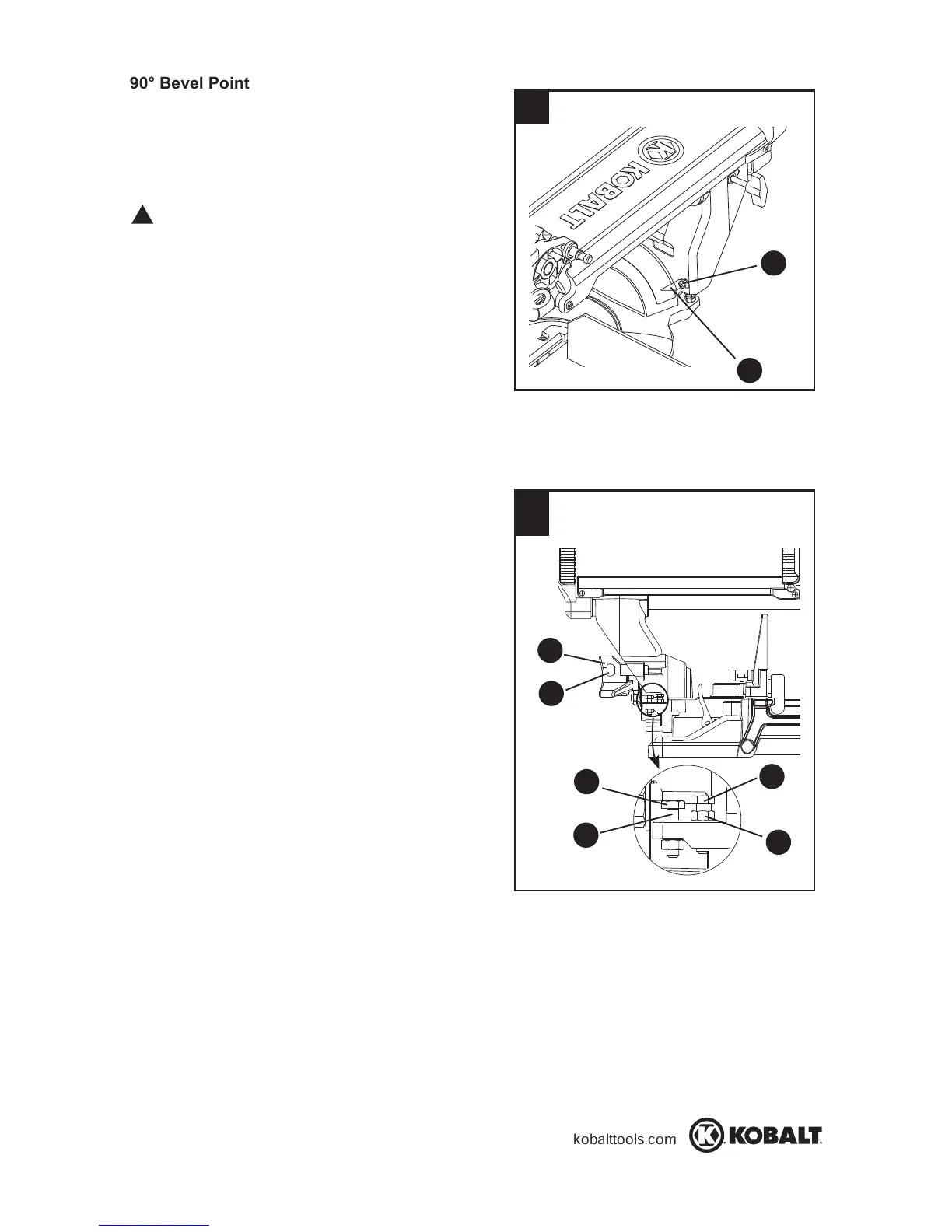
90° Bevel Pointer Adjustment (Fig. 15):
● When the blade is exactly 90° to the table,
loosen the bevel indicator screw (1) using a
Phillips screwdriver.
● Adjust bevel indicator (2) to the “0” mark on
the bevel scale and retighten the screw.
To avoid injury from an accidental start, make
sure the switch is in the OFF position and the
plug is not connected to the power source outlet.
45° Bevel Adjustment (Fig. 16) :
● Loosen the bevel lock handle (
1) and tilt the
cutting head completely to the left.
● Using a combination square, check to see if
the blade angle is 45° to the table.
● If the blade is not at 45° to the miter table, tilt
the cutting arm to the right, loosen the jamb
nut (2) and turn the bevel angle adjustment
bolt (3) in or out with a 10 mm wrench
accordingly.
● Tilt the cutting arm to the left to 45° bevel
and recheck for alignment.
● Repeat steps 1 through 4 until the blade is
at 45° to the miter table.
● Tighten bevel lock handle (1) and jamb
nut (2) when alignment is achieved.
33.9° Bevel Adjustment (Fig. 16) :
● Push the bevel detent pin (4) in toward the
front of the unit.
● Unlock the bevel lock handle and tilt the
cutting arm to the crown molding positive
stop at 33.9°.
● Using a combination square, check to see if
the blade angle is 33.9° to the table.
● If the blade is not at 33.9
o
to the miter table,
l
oosen jamb nut (5) then turn the bevel
angle adjustment bolt (6) in or out with a 10
mm wrench until the blade is at 33.9
o
to the
mi
ter table.
● Secure the jamb nut (5) into position after
alignment is achieved.
15
16
WARNING
!
1
2
1
4
3
2
6
5
 Loading...