B. Adjusting the Position of the Laser Beam
(Fig. 25, 26, 27)
NOTE: There are two adjustment screws on
the laser guide. Use a 3 mm hex wrench to
make any needed adjustments.
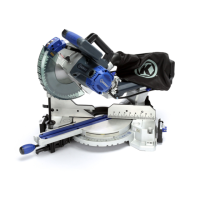
Procedure A (Fig. 25, 26)
● Slightly turn adjustment screw (3) to
adjust the vertical angle of laser beam
on the front of the board. If the laser
beam is angled from left to right, turn the
adjustment screw (3) clockwise; If the
laser beam is angled right to left, turn the
adjustment screw (3) counterclockwise
until the laser beam is parallel with the
vertical pattern line.
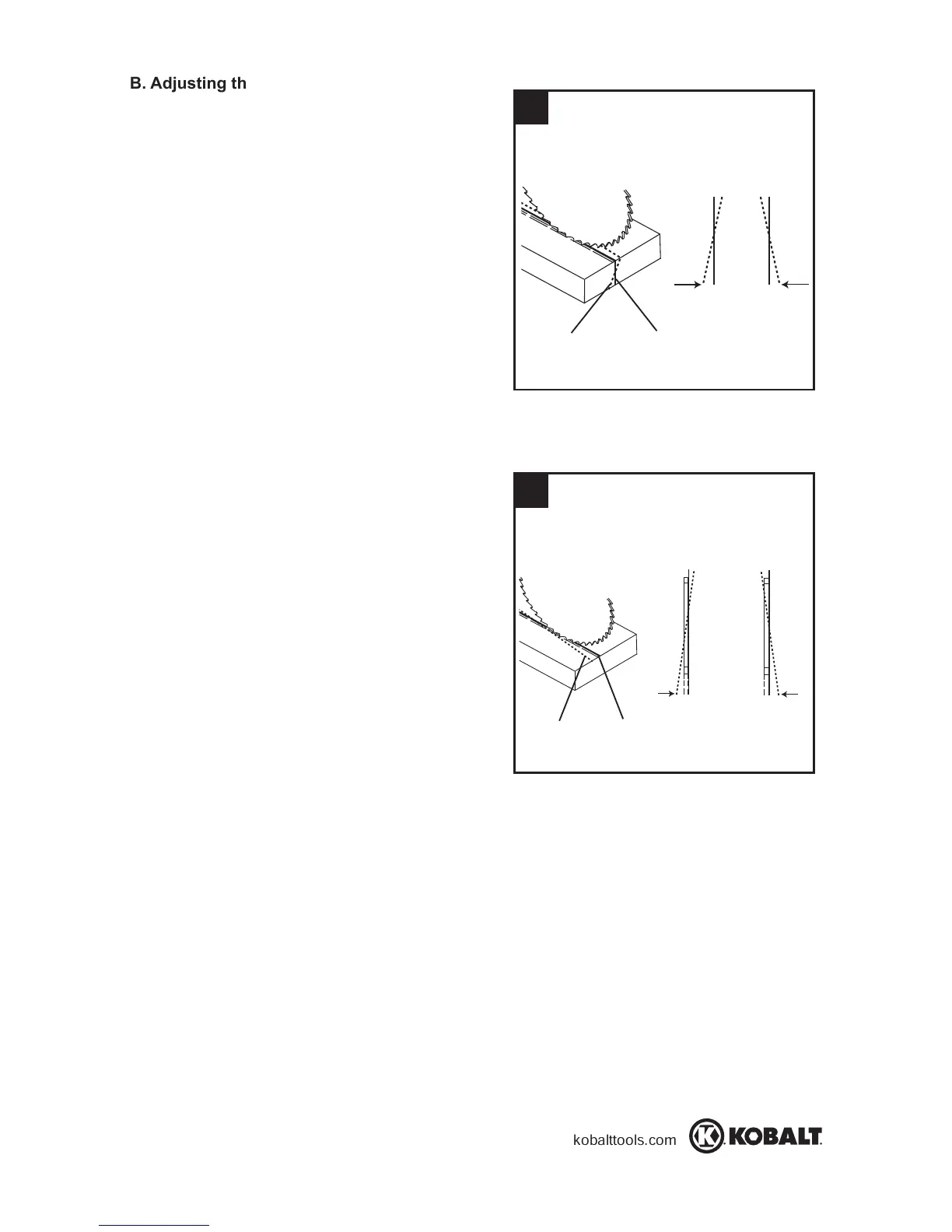
Procedure B (Fig. 25, 27)
● Slightly turn adjustment screw (4) to adjust
the horizontal angle of laser beam on
the top of the board. If the laser beam is
out of parallel from left to right, turn the
adjustment screw (4) clockwise; If the
laser beam is out of parallel from right
to left, turn the adjustment screw (4)
counterclockwise until the laser beam is
parallel with the horizontal pattern line.
● Recheck the laser beam alignment.
27
26
Laser beam
Clockwise
Counterclockwise
Pattern line
Procedure A
ClockwiseCounterclockwise
Laser beam
Pattern line
Procedure B
 Loading...