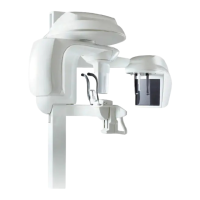
Installing the Cephalostat Unit
KODAK 9000C and KODAK 9000C 3D Extraoral Imaging System Installation Guide (SM714)_Ed 01 5–7
Wiring the Cephalostat to the Unit Head
8. Pull the cables out of the cephalostat arm. Pass the cables through the opening in the
column and attach them with a cable tie to avoid cable wear due to usage as shown in the
figure below. Connect the wiring in the following order:
Cable ... On the ... To ...
(A) 967/CJ653/J10 CJ653 J10
(B) Ethernet Pano Ethernet Pano
(C) Ethernet Workstation Ethernet Workstation
(D) 964/CJ732/J29 CJ732 J29
CJ653
CJ699
CJ732
LF440
J15
J29J28
J18
J14 J21
CJ732
J4
J6
J10
J5
CJ653
D
A
B
C
 Loading...

