TP-6322 9/04 1Section 1 General
Section 1 General
1.1 Purpose
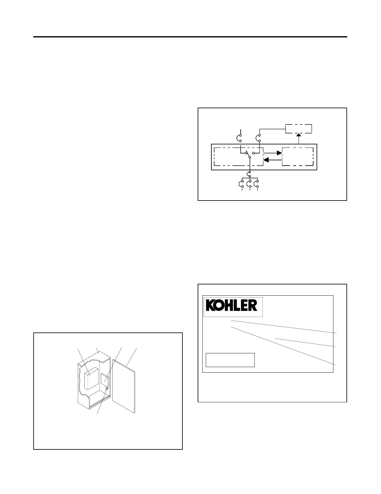
An automatic transfer switch (ATS) transfers electrical
loads from a normal (preferred or utility) source of
electrical power to an emergency (standby or
replacement) source when the normal source fails to
maintain a minimum power quality level.
When the normal source fails, the ATS signals the
emergency source generator set to start. When the
emergency source reaches a minimum quality level, the
ATS transfers the load from the normal source to the
emergency source. The ATS continuously monitors the
normal source and transfers the load back to the normal
source when the normal source returns. After
transferring the load back to the normal source, the ATS
removes the generator start signal, allowing the
generator set to s hut down.
1.2 Components
The ATS documented in this manual contains several
components. See Figure 1-1. The contactor power
switching device c onnects the load to the normal or
emergency sources of power. The electrical controls
monitor power sources, control the contactor, and signal
the generator to start when needed. The exerciser
switch controls the operation of the exerciser function.
The contactor power switching device transfers power
from the normal or emergency power sources to the
load. The electrical controls electrically actuate the
contactor to select a power source, and the contactor
mechanically latches in the selected position. The
contactor also includes a provision for manual operation
in emergency nonpowered conditions.
1 43
5
5990101
2
1. Power switching device (contactor)
2. Enclosure
3. Electrical controls (solid-state)
4. Enclosure cover
5. Exerciser switch
Figure 1-1 AT S Components
The contactor power switching device uses two sets of
multipole contacts. See Figure 1-2. One set of contacts
connects the load to the normal source and the other set
connects the load to the emergency source. The
double-throw, inherently interlocked design of the
contactor prevents simultaneous closing of both sets of
contacts and cross-coupling of power sources.
Power
Switching
Device
To Load
Automatic Transfer Switch
Electrical
Controls
Normal
(Utility)
Power
Emergency
(Generator)
Power
Generator
Start Generator
TS-002
Figure 1-2 Typical ATS Block Diagram
1.3 Nameplate
A nameplate attached to the inside of the enclosure door
or cover i ncludes a model number, a serial number,
ratings, and other information that may be needed for
operation, installation, service, or to order parts. See
Figure 1-3.
ENCLOSURE
POLES HERTZ
SERIAL NO.
AMPS
WIRES
MODEL
PHASE
ACCESSORIES:
TS-003
1
3
TRANSFER SWITCH
VOLTS
2
KOHLER CO. KOHLER WI, USA
r
FOR EMERGENCY SYSTEMS
1. Model number
2. Factory-installed accessory numbers
3. Serial number
Figure 1-3 Typical Transfer Switch Nameplate

 Loading...


