TP-6322 9/04 19Section 4 Troubleshooting
4.4.1 AC System Voltages
1. Disconnect all power sources and check that the
controller is connected to the contactor assembly
wiring harness at connector P1.
2. Check that the circuit breakers leading to the
transfer switch from the normal and emergency
sources are closed.
3. The transfer switch needs at least one source
present to transfer the load to an available source.
If the normal source is available, check for nominal
line voltage between lugs NA and NC on the
contactor assembly. If the emergency source is
available, check for line voltage between lugs EA
and EC on the contactor assembly. If not all phases
are present on the corresponding source, the
problem lies upstream of the transfer switch.
4. If all phases are present on the normal source lugs,
check for nominal line voltage between terminals
J1-12 and J1-15 on the contactor wiring harness
connector on the controller assembly. If all phases
are present, check for nominal line voltage
between terminals NA and NC on TB1 on the
controller assembly. If voltage is present on J1 but
not on TB1, replace the controller assembly.
5. If all phases are present on the emergency source
lugs, check for nominal line voltage between
terminals J1-3 and J1-6 on the contactor wiring
harness connector on the controller assembly.
6. If the voltage on any phase at the controller is not
steady and correct, the problem could lie in the
connection between the contactor and the
controller. Check the contactor wiring harness and
connections.
4.4.2 DC Controller Voltages
1. If AC voltage is present at terminals NA-NC on TB1
on the controller assembly, check the DC voltage
between terminals GND and the +12UF on TB5 on
the controller assembly. A good controller
assembly should have between 12.0 and
14.0 VDC between these terminals. If the voltage
is higher or zero, replace the controller assembly.
2. If the voltage on terminal +12UF is low, disconnect
any customer load connected to terminal +12UF on
TB5 and remeasure. If voltage is restored the
problem is an excessive load on +12UF. If voltage
is not restored, replace the controller assembly.
3. If the +12UF terminal voltage is within
specifications, check the voltage between terminal
GND on TB5 and the +5VDC (right-most) terminal
on voltage regulator VR1 located near the center of
the controller circuit board. It may be necessary to
scrape the +5VDC terminal slightly with the test
probe due to the conformal coating on the circuit
board to make good contact. A good controller
should have 5±5% VDC at the +5VDC terminal,
otherwise replace the controller assembly.
4. If the +5VDC terminal voltage is within
specifications, disconnect customer loads
connected to terminal +12UF on TB5 on the
controller assembly, and disconnect all power
sources to the transfer switch. The 5 VDC supply
should stay within specifications for at least
90 seconds. If this voltage is not held, replace the
controller assembly, otherwise reconnect
customer loads to terminal +12UF.
4.5 Engine Start Circuit
Follow this section first when the transfer switch does
not start the generator set engine when it should or the
generator set engine is signalled to run when it should
not.
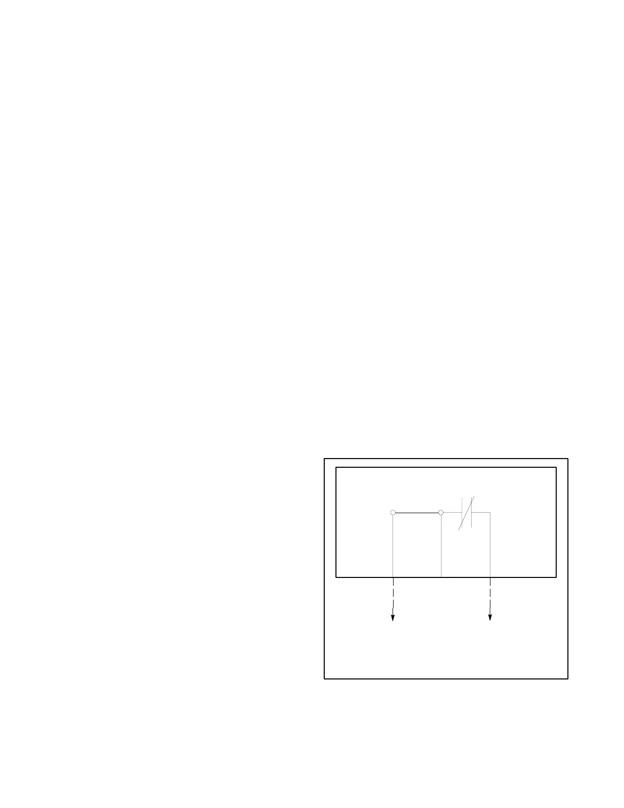
This procedure will also verify that the ES LED on the
controller assembly correctly reflects the engine start
circuit status. The ES LED should be off when the
engine start circuit between terminals ES3 and ES4 on
the controller assembly is closed to signal the engine to
start. See Figure 4-3. The ES LED should light when
the engine start circuit is open to signal the engine to
shut down.
362140
12 3
ES3
ES3D
ES4
TB3
To Generator
JP4
MAIN CONTROLLER CIRCUIT BOARD
ES
ES LED is off
Engine signalled to run
Note: Shown with no power present.
Figure 4-3 Engine Start Circuit

 Loading...

