TP-6322 9/0436 Section 6 Service Part Replacement
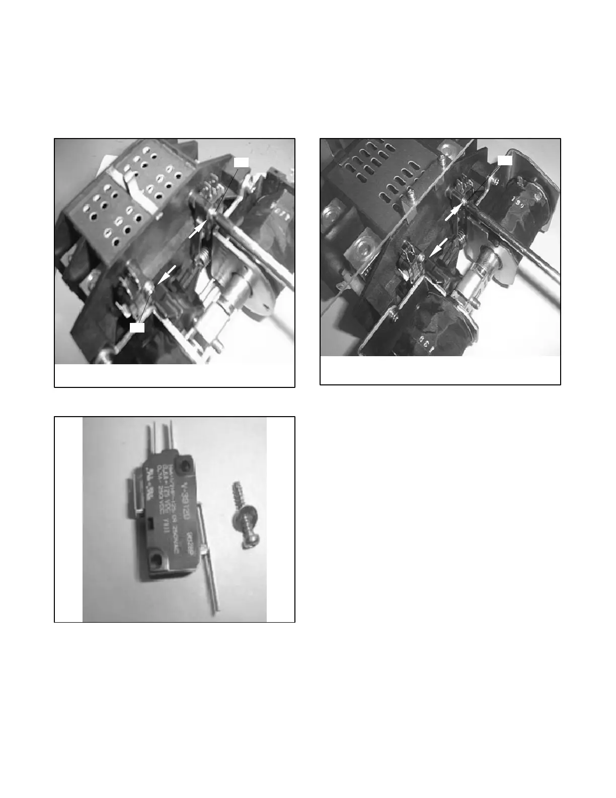
2. Remove the microswitch mounting screw and
microswitch. See Figure 6-10 and Figure 6-11.
3. Install the new microswitch. Push the microswitch
mounting screw in the direction of the arrow shown
in Figure 6-10 and tighten it to 0.44 Nm (4 in. lb.).
4. Tighten the four coil mounting screws.
1
tp5992
1. Microswitch mounting screw
1
Figure 6-10 Microswitch Mounting Screw
tp5992
Figure 6-11 Microswitch and Mounting Screw
6.4.2 200 Amp Models
1. Remove the microswitch mounting screw and
microswitch. See Figure 6-12.
2. Install the new microswitch. Push the microswitch
mounting screw in the direction of the arrow shown
in Figure 6-12 and tighten it to 0.44 Nm (4 in. lb.).
1
tp5992
1. Microswitch mounting screw
Figure 6-12 Install new Microswitch, 200 Amp
Models
6.5 Controller PCB Assembly
Electronic printed circuit boards (PCBs) are sensitive to
a variety of elements and can be damaged during
removal, installation, transportation, or storage.
Observe the following when working with circuit boards.
Circuit Board Handling
D Store circuit boards in the anti-static, cushioned
packaging provided by the factory in a clean
environment away from moisture, vibration, static
electricity, corrosive c hemicals, solvents, or fumes
until installation.
D Wear an approved grounding, anti-static wrist strap
when handling circuit boards or components.
D Carefully hold the circuit board only by its edges, not
by any of its components.

 Loading...

