TP-6322 9/04 35Section 6 Service Part Replacement
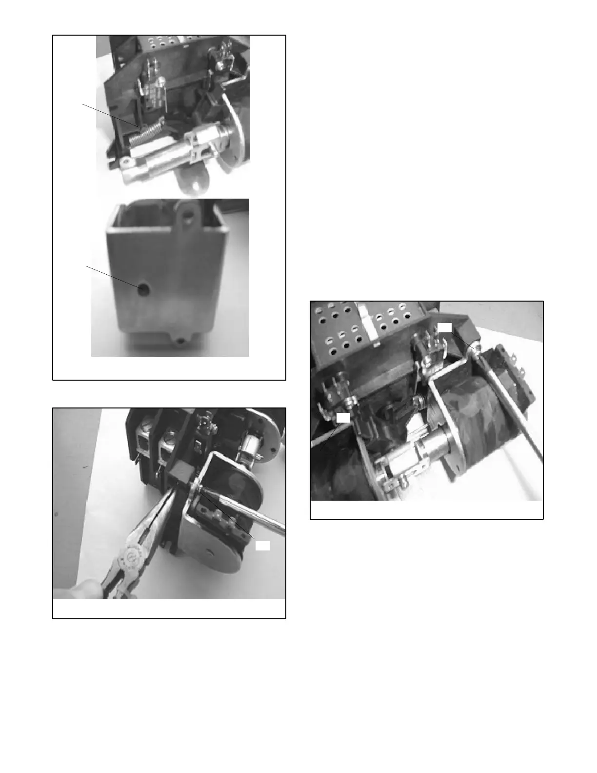
1. Locating protrusion in frame
2. Locating hole in solenoid bracket
1
tp5992
2
Figure 6-7 Locating the Solenoid Assembly, Typical
1
tp5992
1. Install and tighten 2 mounting screws
Figure 6-8 Installing the Coil Assembly,Typical
6.4 Microswitch Replacement
Procedures shown are for the microswitch at the
Emergency source coil. Use the same procedures for
the microswitch at the Normal source coil.
Perform the switch replacement procedures on one
source side at a time.
D To replace the microswitch at the Normal source coil,
first move the contactor to the Emergency source
position.
D To replace the microswitch at the Emergency source
coil, first move the contactor to the Normal source
position.
6.4.1 100 Amp Models
1. Loosen the four coil mounting screws (two for each
coil) by two full rotations. Do not remove the coils.
See Figure 6-9.
1
tp5992
1. Coil mounting screws
1
Figure 6-9 Loosen Coil Mounting Screws, 100 Amp
Models

 Loading...

