TP-6322 9/04 33Section 6 Service Part Replacement
6.3 Solenoid Assembly
Disable the generator set and disconnect all power
sources as described in Section 6.1 before opening the
transfer switch enclosure.
Procedures shown are for the Normal source coil. Use
the same procedures for the Emergency source coil.
Perform the coil replacement procedures on one source
side at a time.
D To replace the Normal source coil, first move the
contactor to the Emergency source position.
D To replace the Emergency source coil, first move the
contactor to the Normal source position.
6.3.1 Solenoid Assembly Removal
1. Remove two mounting screws from the assembly.
SeeFigure6-1.
Note: Two square nuts will be released when the
mounting screws are removed. Save the
screws and nuts for reinstallation later.
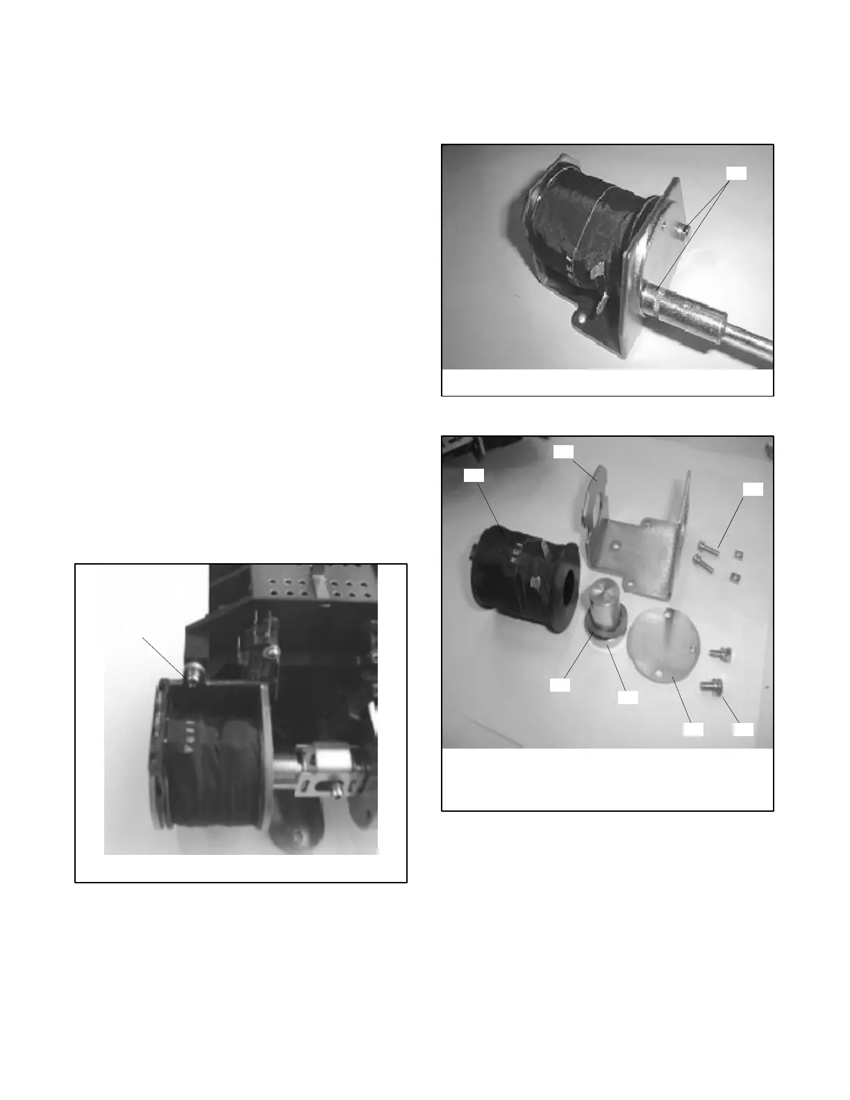
6.3.2 Disassembly, 200 Amp Models
1. Remove two screws from the core plate. See
Figure 6-2.
1
tp5992
1. Remove screws, 2 locations
Figure 6-1 Solenoid Assembly, Model G220, Typical
2. Remove the core plate and the steel core with
washer. See Figure 6-3.
3. Remove the coil from the coil bracket. See
Figure 6-3.
1
tp5992
1. Remove 2 screws
Figure 6-2 Disassembling the Coil Assembly
1
tp5992
1. Coil
2. Coil bracket
3. Assembly mounting
screws and nuts
4. Core plate screws
5. Core plate
6. Steel core
7. Washer
2
3
4
5
6
7
Figure 6-3 Coil Assembly Parts

 Loading...

