TP-6322 9/04 7Section 2 Operation
4. Slide the large end of the manual operation handle
over the manual operation lever on the left side of
the contactor. See F igure 2-3. Move the handle up
to place the transfer switch in the Normal Source
position, or down to place the contactor in the
Emergency Source position.
Note: Do not attempt to move the manual
operation lever without using the handle.
5. Move the handle up to place the transfer switch in
the Normal Source position for normal operation.
6. Remove the handle and store it in a convenient
location near the transfer switch.
7. Replace the cover on the transfer switch enclosure
and tighten the screws that hold it in place.
8. Reconnect power supplies to the transfer switch.
Note: When power is applied to the transfer
switch, the engine start contacts remain
closed until Time Delay Engine Cooldown
(TDEC) ends.
9. Return the generator set to automatic operation.
a. Reconnect the generator engine start battery
cables, negative (--) leads last.
b. Reconnect power to the generator engine start
battery charger, if installed.
c. Move the generator set master switch to the
AUTO (automatic) position. The generator set
may start and run until the Time Delay Engine
Cooldown (TDEC) ends (see Note above).
1. Manual operation handle
2. Manual operation lever
tp6223
2
4
3
7
8
CN
CE
NL1
NL2
EL2EL1
SCN
C
NO
NC
SCE
C
NC
NO
1
Figure 2-3 Contactor with Manual Operation Handle
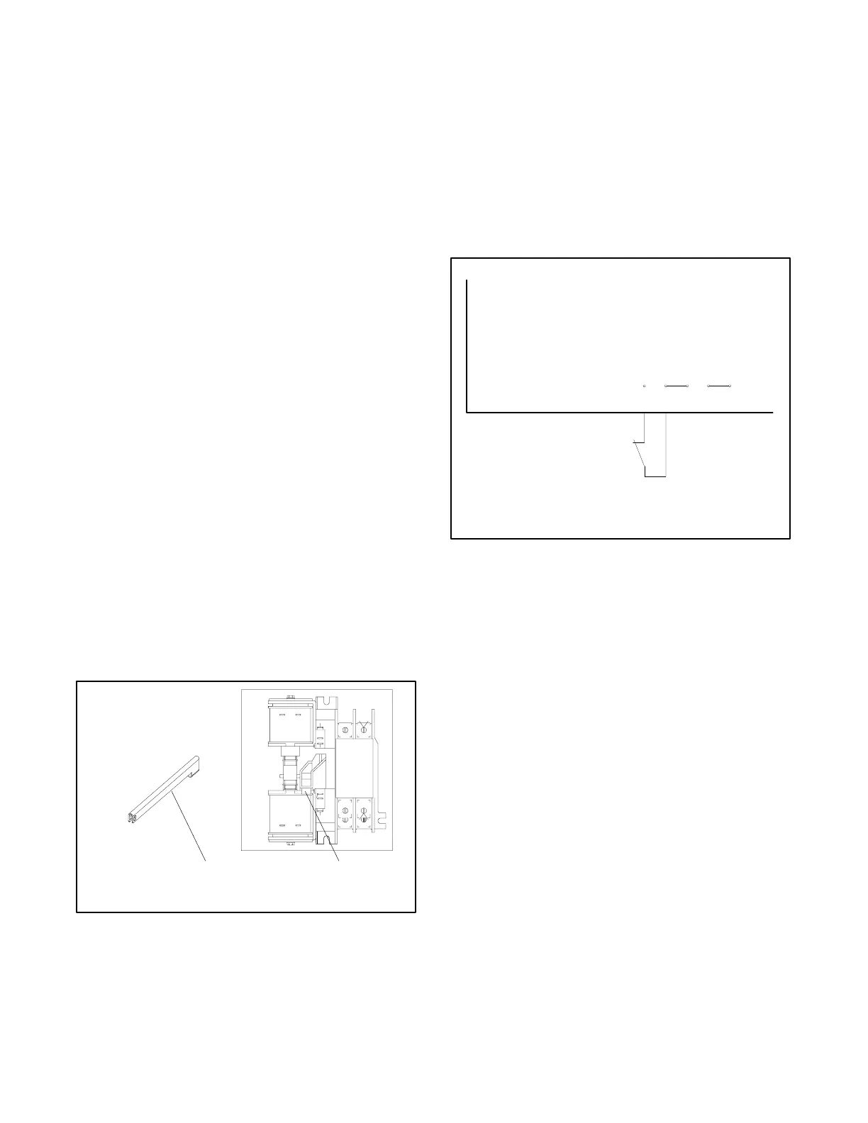
2.5 External Test Switch
A provision on the main controller circuit board allows
the connection of a customer-supplied, normally closed
external test switch. This test switch connects between
the TEST and GND terminals after cutting the jumper
JP2 on the controller circuit board. See Figure 2-4.
When the test switch contact is open, normal-source
single-phase power is disconnected from the controller,
and the controller follows the same sequence of
operation as when the normal source fails.
362140
123 123456
NA
NB
NC
NSC
TEST
GND
ESC
GND
3PH
TB1
TB2
TEST
SWITCH
JP2 JP1
NC
JP3
MAIN CONTROLLER CIRCUIT BOARD
Figure 2-4 External Test Switch

 Loading...

