TP-6835 9/17 25Section 2 Installation
2.7.4 Auxiliary Contacts
Connect the auxiliary contacts to customer-supplied
alarms, remote indicators, or other devices. Auxiliary
contacts provide contacts that close when the transfer
switch is in the Normal position and contacts that close
when the transfer switch is in the Emergency position.
The auxiliary contact rating is shown below.
Auxiliary Contacts
Contact Rating 10 amps @ 32 VDC/250 VAC
Figure 2-25 lists the number of auxiliary contacts
provided with each transfer switch.
Switch
Rating,
amps
Number of Auxiliary Contacts Indicating
Normal, Emergency
KBS KBP KBC
150--400 8, 8 6, 6 5, 5
800--1200 8, 8 7, 7 7, 7
1600--4000 2, 2 7, 7 6, 6
Figure 2-25 Number of Auxiliary Contacts Available
on Each Switch
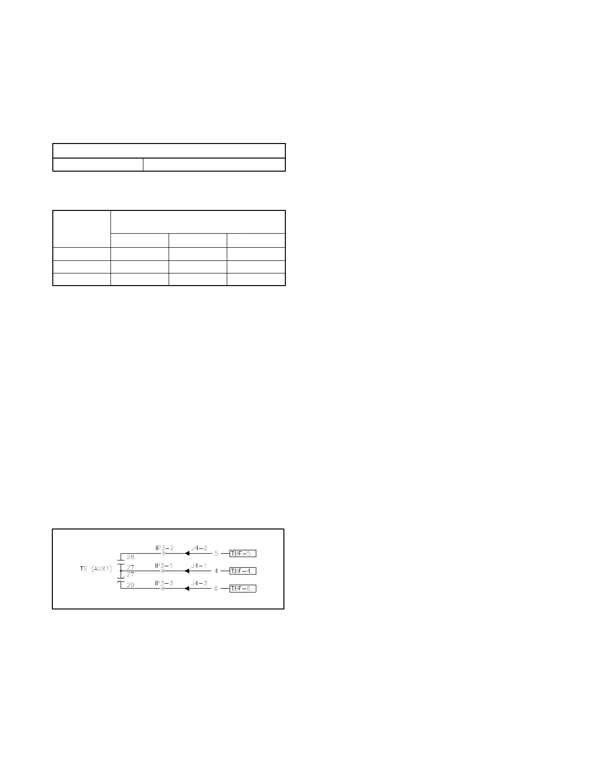
Connect to the auxiliary contacts at the field connection
terminal block. The terminal block is mounted on the
upper right side inside the enclosure on most models.
See Figure 2-24. Figure 2-26 shows typical auxiliary
contact connections. Refer to the schematic drawing
provided with the unit to identify the auxiliary contact
terminals for your model transfer switch.
Note: The contacts are shown with the transfer switch in
the Normal (Source N) position in all figures and
schematic drawings. (Contacts shown closed in
the figures are closed on Normal. Contacts
shown open in the figures will close on
Emergency.)
Follow the wire size and tightening torque specifications
shown on the decal on the transfer switch.
Figure 2-26 Auxiliary Contacts, Typical
2.8 Communication and
Accessory Connections
See Section 4 for accessory and communication
connection instructions.
2.9 Functional Tests
After completion of the mechanical installation and all
electrical connections, perform the functional tests
described in Section 5. The procedures in Section 5 are
required to complete the installation and startup of the
transfer switch.