TP-6835 9/1766 Section 7 Bypass, Isolation, and Manual Transfer
7.3.3 Return to Service,
800--1200 Amp Models
This procedure explains how to return the automatic
transfer switch (ATS) to service after inspection and
maintenance. Observe the bypass switch position
indicator and lights.
1. Use the two handles to roll the transfer switch into
the enclosure (isolation contacts facing inward)
until its crank pins engage the latch plates on both
sides. See Figure 7-43. Next push in both side
rails and close the enclosure door.
WARNING
Hazardous voltage.
Can cause severe injury or death.
Close and secure the enclosure door
before energizing the transfer switch.
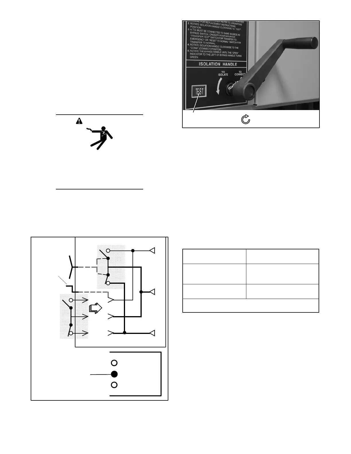
2. Turn the Isolation Handle clockwise (approx. 6
turns) until the window shows TEST and TS TEST
light comes on. See Figure 7-44 and Figure 7-45.
The ATS can be tested now without load interruption.
E
L
N
Turn crank
clockwise
until
window
shows
TEST.
Automatic Transfer Switch
Bypass Switch
TS CONNECTED
Middle amber light
should come on.
TS TEST
TS ISOLATED
Figure 7-44 From ISOLATE to TEST Position
Position
window: TEST
Clockwise – draws in
the transfer switch
Figure 7-45 Isolation Handle Turned to TEST
3. Observe which bypass switch position window
indicator is yellow (NORMAL or EMERGENCY) at
the bypass switch handle. This indicates the
source connected to the load.
Note: A solenoid interlock prevents you from closing
the isolation contacts until the ATS is in the same
position as the bypass switch.
4. Observe which Transfer Switch Connected To light
is on (Normal or Emergency) on the door. This is
the position of the transfer switch. If it is not in the
same position as the bypass handle, change the
position of the transfer switch as shown in
Figure 7-46.
Operate to NORMAL
Operate to
EMERGENCY *
Turn Transfer Control
switch to Retransfer
Delay Bypass.
Turn Transfer Control switch
to Transfer Test (hold 15 sec-
onds).
Connected To Normal
light should come on.
Connected To Emergency
light comes on.
* With Normal a vailable, the automatic transfer switch will return
to the Normal position after the retransfer time delay.
Figure 7-46 Changing Transfer Switch Position
Note: Do not close the isolation contacts unless the
transfer switch (ATS) and bypass switch are in
the same position!
5. When the transfer switch is in the same position as
the bypass switch handle, continue turning the
isolation handle clockwise (about 8 turns) until the
window shows CONN (connected). See
Figure 7-47 and Figure 7-48.