TP-6835 9/17 75Section 7 Bypass, Isolation, and Manual Transfer
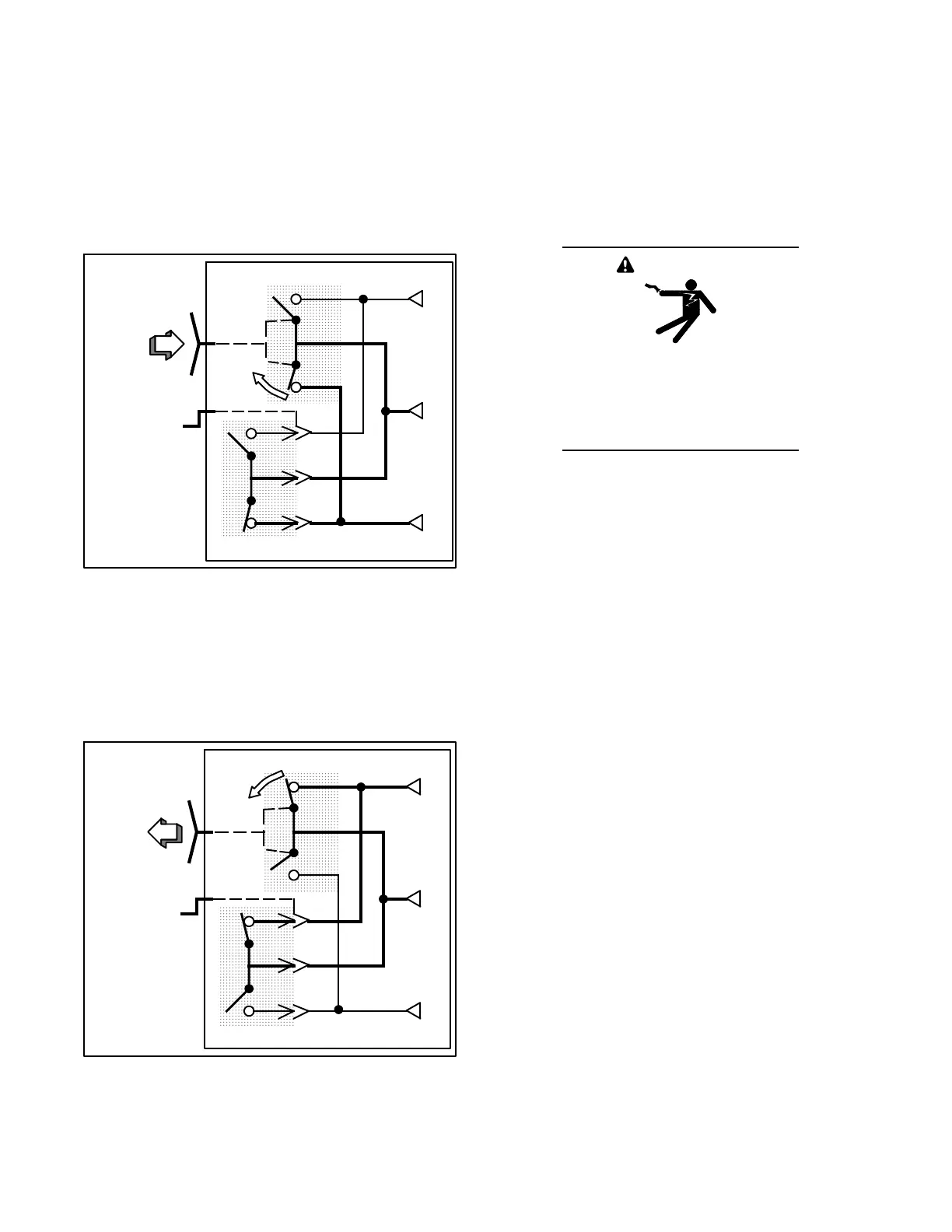
3. Open the bypass contacts that are connected to
the load as follows (select Normal or Emergency).
a. If the load is connected to the NORMAL
source, push in the bypass handle and then
turn it counterclockwise until the bypass switch
position indicator turns green, showing that the
bypass contacts are open. See Figure 7-64
and Figure 7-63. The Not in Auto light should
be off.
E
L
N
Push in
the bypass
handle
and
turn it
counter-
clockwise.
ATS
Bypass Switch
Figure 7-64 Opening Bypass to Normal Contacts
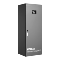
b. If the load is connected to the EMERGENCY
source, pull out the bypass handle and then
turn it counterclockwise until the bypass switch
position indicator turns green, showing that the
bypass contacts are open. See Figure 7-65.
The Not in Auto light should be off.
E
L
N
ATS
Bypass Switch
Pull out
bypass
handle
and
turn it
counter-
clockwise.
Figure 7-65 Opening Bypass to Emergency
Contacts
Leave the bypass and isolation handles in these
positions for automatic operation.
7.4.5 Manual Load Transfer,
1600--4000 Amp Models
This procedure manually transfers the load to the other
source if the transfer switch or the controller are out of
service.
WARNING
Hazardous voltage.
Can cause severe injury or death.
Close and secure the enclosure door
before energizing the transfer switch.
1. Verify that the bypass handle is closed on either
Normal or Emergency. See Section 7.4.1.
2. Verify that the isolation handle is in the TEST or
ISOLATE position. See Section 7.4.2.
3. Turn the bypass handle counterclockwise to
OPEN. Then bypass to the other source. See
Figure 7-63.