TP-6835 9/17 73Section 7 Bypass, Isolation, and Manual Transfer
7.4.4 Return to Operation, 1600--4000
Amp Models
This procedure explains how to return the ATS to
operation after inspection or service.
1. Observe which bypass switch position indicator is
yellow (NORMAL or EMERGENCY). This
indicates the source connected to the load.
2. Slide the transfer switch (ATS) into the enclosure
(isolation contacts facing inward) until its crank
pins engage the latch plates on both sides. On
4000 amp units, substantial force is required to
overcome detents on the rails.
3. 4000 amp models only: Retract the two support
legs and lock them into place.
4. Push in the side rail carriage and then close the
enclosure door.
WARNING
Hazardous voltage.
Can cause severe injury or death.
Close and secure the enclosure door
before energizing the transfer switch.
5. Turn the isolation handle clockwise (approximately
7 turns for 1600 --3000 amp units, 8 turns for 4000
amp units) until the window shows TEST. See
Figure 7-55 and Figure 7-61. The ATS can be
tested now without load interruption.
Note: Turn the isolation handle until the position
shows clearly through the position window.
Do not leave the handle in an intermediate
position.
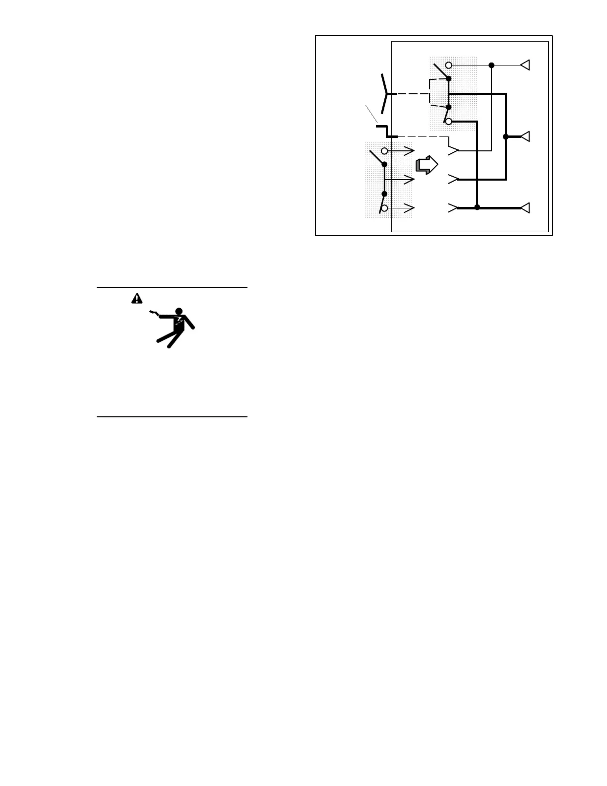
E(B)
L
N(A)
Turn crank
clockwise
until
window
shows
TEST.
ATS
Bypass Switch
Figure 7-61 Moving from ISOLATE to TEST
Position
6. Observe which bypass switch position indicator is
yellow (NORMAL or EMERGENCY). This
indicates the source connected to the load.
Note: Solenoid interlocks prevent closing the isolation
contacts unless the transfer switch is in the same
position as the bypass switch. Do not force the
isolation handle.
7. Observe which Position LED on the controller is
illuminated (Normal or Emergency). This is the
position of the transfer switch. If the transfer switch
is not in the same position as the bypass handle,
check the controller display.
a. If a test sequence is running, press the End Test
button. Wait for the transfer switch to change
positions and the test sequence to end.
b. If the ATS is not under test, do not proceed to
close the isolation contacts. Turn the isolation
handle counterclockwise to the OPEN position
and follow the instructions in Section 2.5 to
manually operate the transfer switch to match
the bypass handle position.
8. When the transfer switch is in the same position as
the bypass switch handle, turn the isolation handle
clockwise (about 16 turns for 1600--3000 amps, 12
turns for 4000 amps) until the window shows
CONN (connected). See Figure 7-62.