TP-6835 9/17 71Section 7 Bypass, Isolation, and Manual Transfer
7.4.3 Removing the Transfer Switch,
1600--4000 Amp Models
After the ATS is bypassed and isolated, it can be
removed from the enclosure for inspection or service.
Hazardous voltage.
Will cause severe injury or death.
Only authorized personnel should
open the enclosure.
DANGER
Short circuits. Hazardous voltage/current will cause
severe injury or death. Short circuits can cause bodily injury
and/or equipment damage. Do not contact electrical
connections with tools or jewelry while making adjustments or
repairs. Remove all jewelry before servicing the equipment.
Removing the transfer switch from bypass/isolation
models. Hazardous voltage can cause severe injury or
death. Bypass and isolate the transfer switch before
removing it from the enclosure. The bypass/isolation switch is
energized. Do not touch the isolation contact fingers or the
control circuit terminals.
Unbalanced weight.
Improper lifting can cause severe
injury or death and equipment
damage.
Use adequate lifting capacity.
Never leave the transfer switch
standing upright unless it is securely
bolted in place or stabilized.
WARNING
The transfer switch weights are shown in Figure 7-58.
Use an overhead crane or other lifting equipment
capable o f handling this weight to move the transfer
switch.
Size, Amps Weight, kg (lbs.)
1600--3000 160--205 kg (350--450 lbs.)
4000 272 kg (600 lbs.)
Figure 7-58 Transfer Switch Weights
Procedure to Remove the Transfer Switch,
1600--4000 Amp Models
1. Open the lower enclosure door.
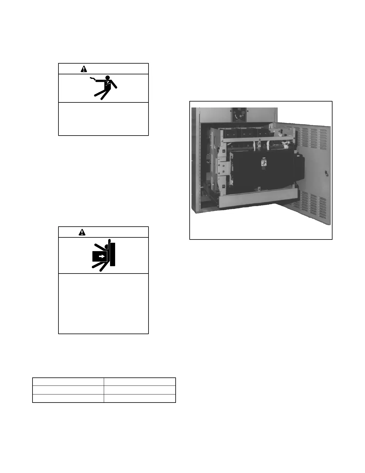
2. Pull out the side rail carriage, then roll out the
transfer switch. See Figure 7-59. It can be safely
inspected in this position. The transfer switch can
also be removed for maintenance operations.
See Section 2.5 for maintenance handle use.
136e
Figure 7-59 1000–4000 Amp Transfer Switch
Isolated and Pulled Out for Inspection
Procedure to Remove the Transfer Switch,
4000 Amp Models
3. See Figure 7-60 and follow these steps:
a. Open both lower doors.
b. Pull out the rail support carriage all the way.
c. Remove the left and right clevis and locking
pins. Drop two support legs and reinstall
locking and clevis pins (to lock in place).
d. Adjust both legs to extend to the floor.
e. Stand directly in front of transfer switch. Grasp
both handles, and pull straight out.
Note: Detents on the rails prevent the transfer
switch from rolling out unless substantial
initial force is applied.
4. The ATS can be safely inspected in this position.
The transfer switch can also be removed for
maintenance operations.