TP-6835 9/17 59Section 7 Bypass, Isolation, and Manual Transfer
E
L
N
Automatic Transfer Switch
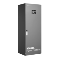
Bypass Switch
Turn crank
clockwise
until
window
shows
CONN.
TS CONNECTED
Upper amber light
should be on.
TS TEST
TS ISOLATED
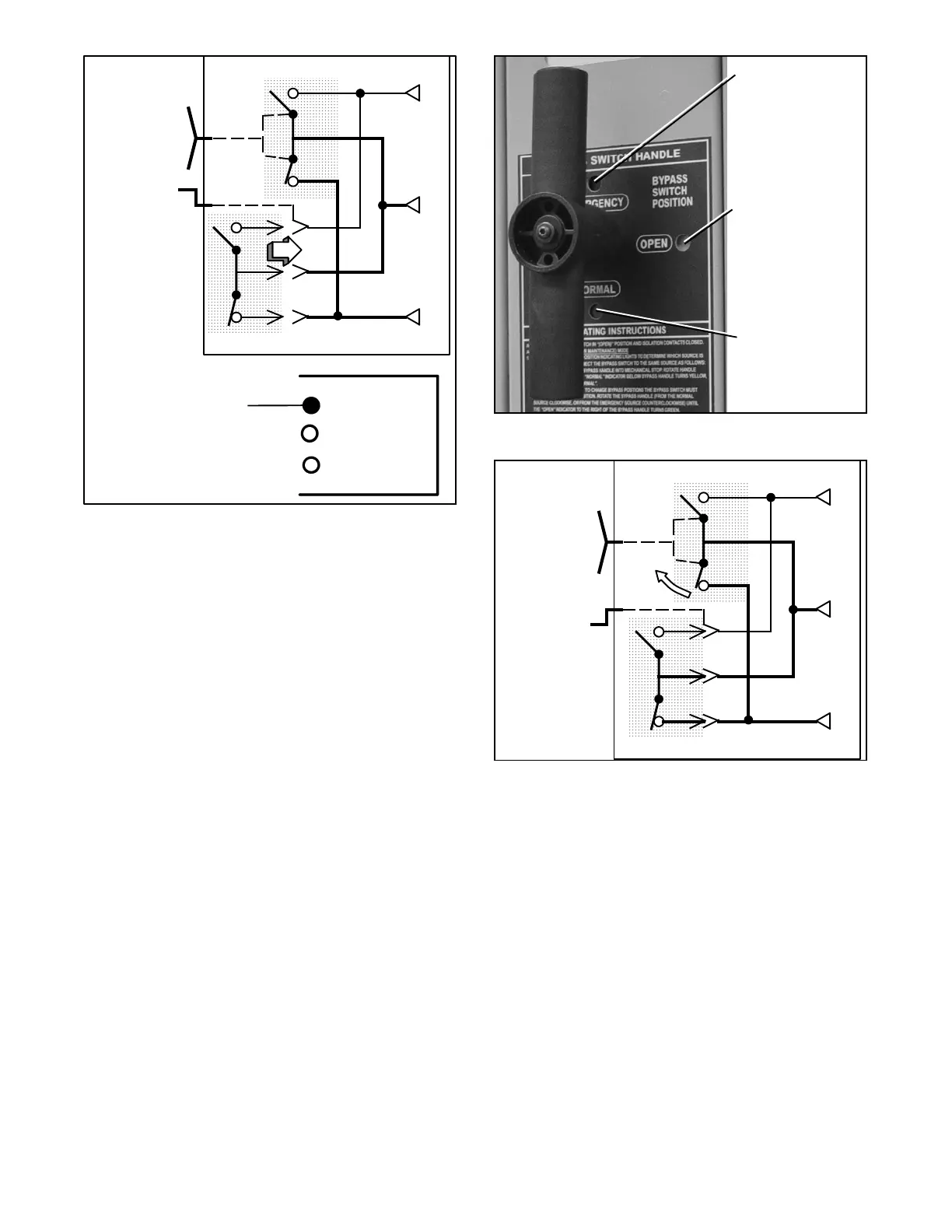
Figure 7-25 TEST to CONN (Connected) Position
7.2.4 Return Bypass Switch to OPEN,
150--600 Amp Mo dels
This procedure e xplains how to return the bypass switch
handle to the OPEN position. The bypass handle must
be in the CLOSED position (yellow indicator on
NORMAL or EMERGENCY) and the isolation handle
must be in the CONN position (window). See
Figure 7-26, Figure 7-27, and Figure 7-28.
Note: You can only bypass to the same source that is
connected to the ATS. A solenoid interlock
prevents incorrect operation.
1. Observe which bypass switch position indicator is
yellow (NORMAL or EMERGENCY) at the bypass
switch handle. This indicates the source
connected to the load. See Figure 7-26.
2. Turn the bypass handle to open the bypass as
directed in the following procedures (select Normal
or Emergency a ccording to the bypass position
indicator).
Window indicator
shows green when
the ATS is not
bypassed.
Window indicator
shows yellow
when ATS is
bypassed to
Emergency.
Window indicator
shows yellow when
ATS is bypassed to
Normal.
Figure 7-26 Bypass Handle and Position Indicators
E
L
N
Turn
bypass
handle
clockwise.
ATS
Bypass Switch
Figure 7-27 Opening Bypass to Normal