TP-6835 9/1758 Section 7 Bypass, Isolation, and Manual Transfer
Position
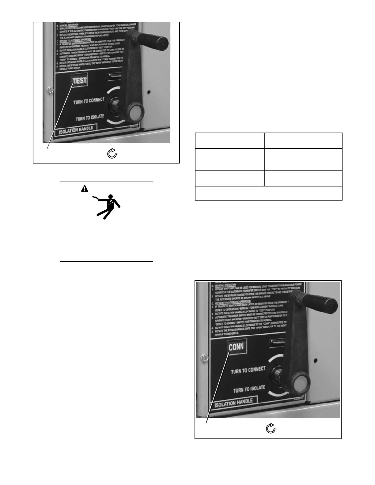
window: TEST
Clockwise draws in
the transfer switch
Figure 7-22 Isolation Handle Turned to TEST
WARNING
Hazardous voltage.
Can cause severe injury or death.
Close and secure the enclosure door
before energizing the transfer switch.
2. Turn the Isolation Handle clockwise (approx.
6 turns) until the window shows TEST and TS
TEST light comes on. See Figure 7-21 and
Figure 7-22.
Note: The ATS can be tested now without load
interruption.
3. Observe which bypass switch position window
indicator is yellow (NORMAL or EMERGENCY) at
the bypass switch handle. This indicates the
source connected to the load.
Note: A solenoid interlock prevents you from
closing the isolation contacts until the ATS is
in the same position as the bypass switch.
4. Observe which Transfer Switch Connected To light
is on (Normal or Emergency) on the door. This is
the position of the transfer switch. If it is not in the
same position as the bypass handle, change the
position of the transfer switch as shown in
Figure 7-23.
Operate to NORMAL
Operate to
EMERGENCY *
Turn Transfer Control
switch to Retransfer Delay
Bypass.
Turn Transfer Control
switch to Transfer Test (hold
15 seconds).
Connected To Normal
light should come on.
Connected To Emergency
light comes on.
* With Normal a vailable, the automatic transfer switch will return
to the Normal position after the retransfer time delay.
Figure 7-23 Changing Transfer Switch Position
Note: Do not close the isolation contacts unless
the transfer switch (ATS) and bypass switch
are in the same position!
5. When the transfer switch is in the same position as
the bypass switch handle, continue turning the
isolation handle clockwise (about 8 turns) until the
window shows CONN (connected).
Position
window: CONN
Clockwise draws in
the transfer switch
Figure 7-24 Isolation Handle Turned to CONN