TP-6835 9/1764 Section 7 Bypass, Isolation, and Manual Transfer
7.3.2 Isolating the AT S,
800--1200 Amp Models
Isolate the transfer switch before performing any service
work on the automatic transfer switch (ATS). Refer to
Figure 7-39 through Figure 7-42.
1. Bypass the closed automatic transfer switch
contacts. See Section 7.3.1 for instructions.
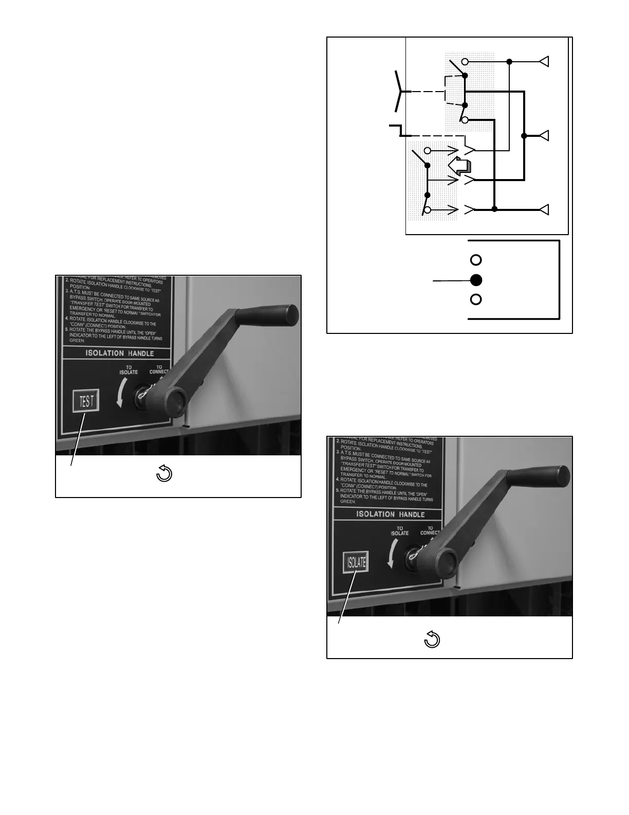
2. Turn the Isolation Handle counterclockwise
(approx. 8 turns) until window shows TEST.See
Figure 7-39. The TS Test amber light should come
on (Figure 7-40). The ATS can be tested now
without load interruption.
Note: In the TEST position the transfer switch solenoid
operator circuit is energized through secondary
disconnects.
Position
window:
CONN
TEST
ISOLATE
Counterclockwise – draws
out the transfer switch
Figure 7-39 Isolation Handle Turned to TEST
E
L
N
Automatic Transfer Switch
Bypass Switch
Turn crank
counter-
clockwise
until window
shows TEST.
TS CONNECTED
Middle amber light
should be on.
TS TEST
TS ISOLATED
Figure 7-40 CONNECTED to TEST position
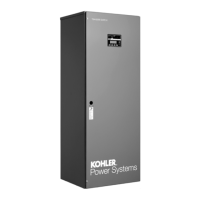
3. Continue turning the Isolation Handle
counterclockwise (approx. 6 turns) until the
window shows ISOLATE. See Figure 7-41. The
amber TS Isolated light should come o n
(Figure 7-42).
Position
window: ISOLATE
Counterclockwise – draws
out the transfer switch
Figure 7-41 Isolation Handle Turned to ISOLATE.