TP-6835 9/17 9Section 1 Product Description
Section 1 Product Description
1.1 Purpose
An automatic transfer switch (ATS) transfers electrical
loads from a normal (preferred) source of electrical
power to an emergency (standby) source when the
normal source falls outside the acceptable electrical
parameters.
When the normal (preferred) source fails, the ATS
signals the emergency (standby) source generator set
to start. When the emergency (standby) source reaches
acceptable levels and stabilizes, the ATS transfers the
load from the normal (preferred) source to the
emergency (standby) source. The ATS continuously
monitors the normal (preferred) source and transfers
the load back when the normal (preferred) source
returns and stabilizes. After transferring the load back to
the normal (preferred) source, the ATS removes the
generator start signal, allowing the generator set to shut
down.
A bypass/isolation transfer switch allows transfer switch
testing and service without interrupting power to the
load. The bypass connection is open during normal
transfer switch operation. Closing the bypass
connection provides a direct connection to either the
Normal or Emergency source, bypassing the transfer
switch to provide power to the load during transfer
switch service. Isolation removes the transfer switch
from the power circuit. Procedures in Section 7 explain
how to bypass and isolate the transfer switch.
Figure 1-1 shows a typical bypass/isolation transfer
switch.
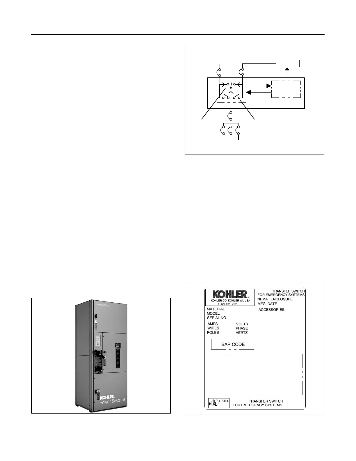
Figure 1-2 shows a typical installation block diagram.
Figure 1-1 Bypass/Isolation Switch
Power
Switching
Device
To Load
Automatic Transfer Switch
Electrical
Controls
Normal (Utility)
Power
Emergency
(Generator)
Power
Generator
Start Generator
6835
Bypass
Isolation
Switch
Figure 1-2 Typical ATS Block Diagram
1.2 Nameplate
A nameplate attached to the controller cover on the
inside of the enclosure door includes a model
designation, a serial number, ratings, and other
information about the transfer switch. See Figure 1-3.
The serial number is also shown on a label inside the
transfer switch enclosure.
Copy the model designation, serial number, and
accessory information from the nameplate to the spaces
provided in the Product Identification Information
section inside the front cover of this manual for use when
requesting service or parts.
GM21291
Figure 1-3 Typical Transfer Switch Nameplate