TP-6835 9/17 51Section 7 Bypass, Isolation, and Manual Transfer
Section 7 Bypass, Isolation, and Manual Transfer
7.1 Introduction
The bypass and isolation handles allow transfer switch
testing and service without interrupting power to the
load. Read the information and instructions in
Sections 7.1.1 and 7.1.2 before proceeding to the
bypass and isolation procedures.
Note: To prevent confusion, set the preferred source
selection (available if the ATS is equipped with
the optional alarm module) to SOURCE N before
beginning the bypass/isolation procedures. See
the controller Operation Manual for instructions, if
necessary.
7.1.1 Bypassing the Transfer Switch
The bypass handle allows direct connection of the
source to the load, bypassing the transfer switch to
provide power to the load during transfer switch service.
The bypass connection is open during normal transfer
switch operation. Closing the bypass connection
provides a direct connection to either the Normal or
Emergency source. See Figure 7-1 and Figure 7-2.
Check the transfer switch position and bypass to the
source that is connected to the automatic transfer switch
(ATS) at the time.
Note: Bypass to the source that is connected to the
load, as indicated by the Transfer Switch Position
indicator. Interlocks prevent bypassing to the
wrong source; do not force the bypass handle.
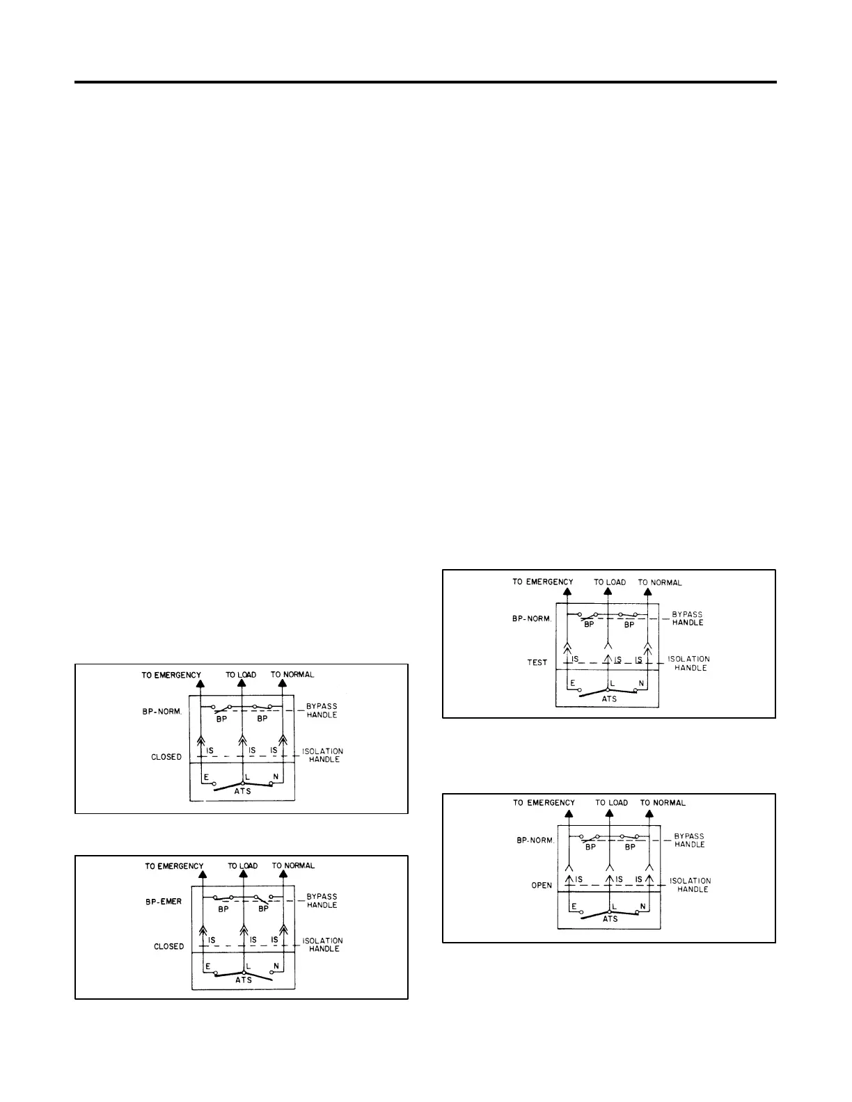
Figure 7-1 Bypass to Normal
Figure 7-2 Bypass to Emergency
The bypass handle positions are labeled Normal and
Emergency. Transfer switches equipped with the alarm
module have a preferred source selection that allows
selection of either source as preferred. The preferred
source selection does not affect the bypass handle
positions. Do not confuse the preferred source with the
source connected to the Normal side of the power
switching device in the following procedures.
7.1.2 Iso lating the Transfer Switch
Isolation removes the transfer switch from the power
circuit. Always bypass the transfer switch before
moving the isolation handle to the TEST or OPEN
position. In the TEST position, the isolation contacts
disconnect the transfer switch from the load but
maintain transfer switch connections to the sources,
allowing transfer switch testing without load. See
Figure 7-3. In the OPEN position, the isolation contacts
disconnect the transfer switch from the load and from
both sources, allowing transfer switch service. See
Figure 7-4.
For normal ATS operation, the isolation handle should
be in the CLOSED position. In the CLOSED position,
the ATS isolation contacts are fully engaged with both
sources and the load.
Figure 7-3 Isolate to Test (load contacts are
disengaged but sources are
connected)
Figure 7-4 Isolate to Open (isolation contacts are
all disengaged)