TP-6835 9/1756 Section 7 Bypass, Isolation, and Manual Transfer
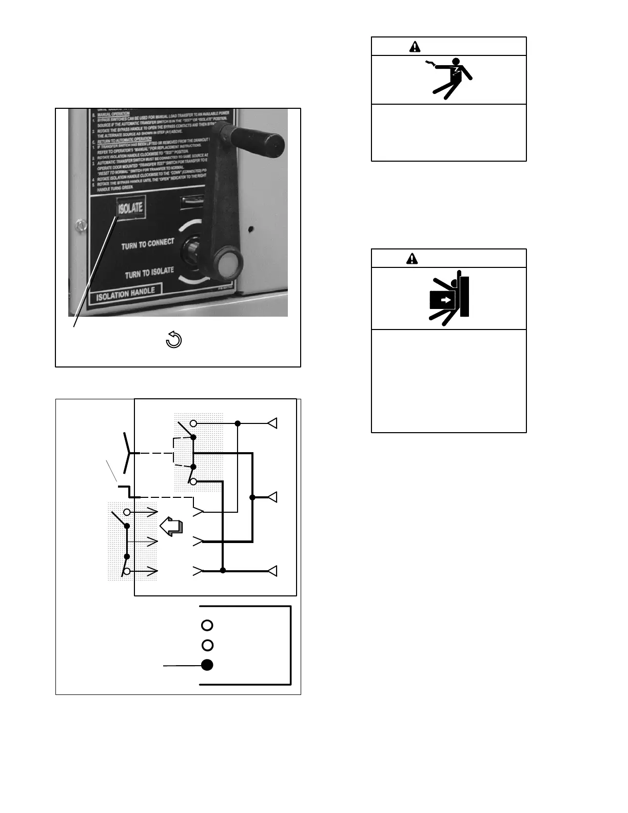
3. Continue turning the Isolation Handle
counterclockwise (approx. 6 turns) until the
window shows ISOLATE. See Figure 7-17. The
amber TS Isolated light should come on. See
Figure 7-18.
Position
window:
ISOLATE
Counterclockwise draws
out the transfer switch
Figure 7-17 Isolation Handle Turned to ISOLATE.
Turn crank
counter-
clockwise
until
window
shows
ISOLATE.
E
L
N
Automatic Transfer Switch
Bypass Switch
TS CONNECTED
Lower amber light
should be on.
TS TEST
TS ISOLATED
Figure 7-18 From TEST to ISOLATE Position
Hazardous voltage.
Will cause severe injury or death.
Only authorized personnel should
open the enclosure.
DANGER
Removing the transfer switch from bypass/isolation
models. Hazardous voltage will cause severe injury or
death. Bypass and isolate the transfer switch before
removing it from the enclosure. The bypass/isolation switch is
energized. Do not touch the isolation contact fingers or the
control circuit terminals.
Unbalanced weight.
Improper lifting can cause severe
injury or death and equipment
damage.
Use adequate lifting capacity.
Never leave the transfer switch
standing upright unless it is securely
bolted in place or stabilized.
WARNING
Note: The transfer switch weighs about 55 kg (120 lb.)
depending upon the number of poles. Use lifting
equipment capable of lifting this weight. Two
persons are recommended.
4. Open the lower enclosure door. Pull out both left
and right side rails then use the two handles to roll
out the transfer switch. It can be safely inspected in
this position. The transfer switch can also be
removed for easier maintenance operations. See
Figure 7-19 or Figure 7-20.