10
157
155
154
158
156
160159
- 79 - - 79 -
Fuel system
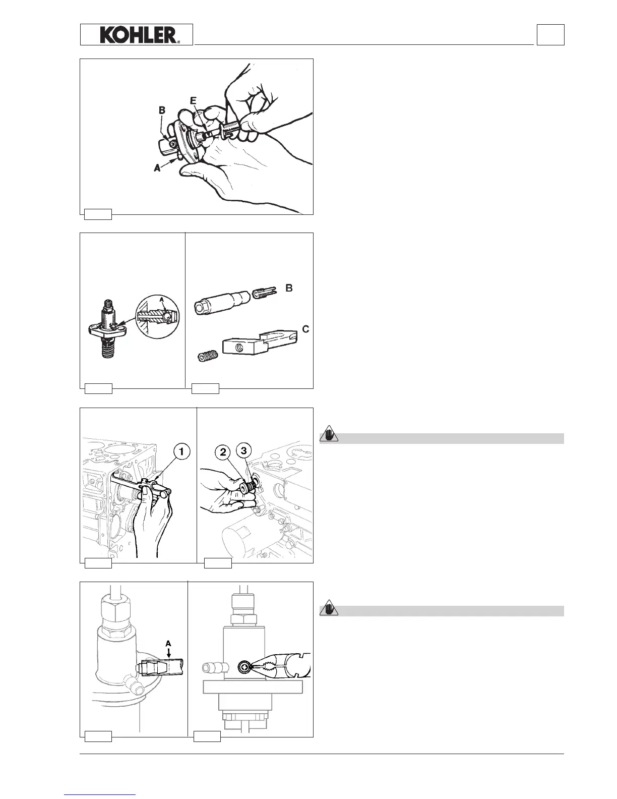
How to reassemble injection pump components
FittheplungerwithhelixE directedtowardsthedischargeunion
B;ifitiserroneouslyttedwithspiralfacingthefuelfeedunion
Atheinjectionpumpwillnotoperate(thusthepossibilityofthe
engine overspeeding is completely ruled out); complete reas-
semblyfollowingg.154
Tightendeliveryunionto35Nm;itisessentialtouseatorque
wrench.
Tool serial number
7107.1460.212
How to remove injection pump feeding tubes
Caution – Warning
Cutting the pipe in the opposite direction to the arrow A
(horizontally) damages the pump coupling with consequent
leakage of fuel.
CutthenylontubeatA.
Removetheportionleftinsidetheunionusingpliers.
Remove the nylon tube without damaging the union seals as
showninthegure159.
Injection pump control rod
Caution – Warning
Do not unscrew ring nut 2 before removing rod 1.
Controlrod1,operatedbythethrottleandgovernedbythespeed
governor,controlstheinjectionpump.
Ring nut 2 keeps rod 1 in the required position by means of
groove3.
Injection pump non-return valve
The discharge union is tted with a non-return valve A; this
valveimproves injectionby bleeding theair insidethefuel and
stopstheengineimmediatelyafterthestopdeviceisoperated.
Toreplacetheoutletunionwithnon-returnballvalveonQLCtype
injectionpumps(havinginletandoutletunionspressure-ttedon
thepumpcase)usethespecialtoolserialnumber7107.1460.212.
ToolB isrequiredforremovalofvalveA,toolCfordriving.
Workshop Manual KDW 1603_2204_2204/T _ cod. ED0053029180 - 1° ed_rev. 00

 Loading...


