11
195
196 197
-30 11860 - 30
-20 7000 23,5÷29,5 19÷23
4÷7
0 2400 13,5÷16,5 9,5÷12,5
+20 1000 8,5÷10,5 5÷7
+40 ≤ 460 6,0÷8,0 2÷4
+50 320
12V 24V
11,5V 25V
12÷14A(5") 12÷14A(5")
12÷14A(5")
12÷14A(5")
12÷14A(5")
194
- 96 - - 96 -
Pre-heating glow plug
Components: 1Sheath
2Regulationlament
3Heatinglament
Installationtorque20Nm.
Note:Theglowplugisnotdamagedinanywayduetotheprolonged
activationtime.
Nominalvoltage
Current
Sheathsurface
temperature
Glow plug Type
after
after
after
after
after
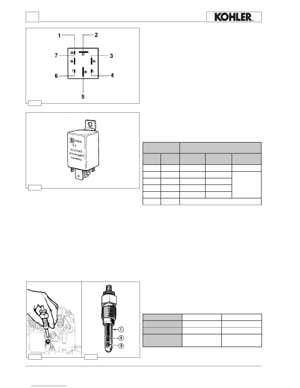
Glow plug controller relay with coolant temperature sensor
Toavoidwhitesmokegenerationatcoldstart-up,post-heatingis
maintainedforapproximately5sec.afterstarting.
Trasducer Heatingtimeinseconds
Resistance
Ω
Temperature
°C
Pre-heating
12V
Pre-heating
24V
Startingcontrol
andPost-heating
Stop
Connection diagram for preheating control unit
Components:
1
Cablecross-section2.5mm
2
atpoint“50”ofthekeypanel
2Cablecross-section6mm
2
atthefuseholderbox
3Cablecross-section1.5mm
2
attheearth
4Cablecross-section1mm
2
atthesparkplugwarninglight(max.2W)
5Cablecross-section6mm
2
atpoint“30”ofthekeypanel
6Cablecross-section1mm
2
atthewatertemperaturesensor
7Cablecross-section1.5mm
2
atthefuse
Electric system
Workshop Manual KDW 1603_2204_2204/T _ cod. ED0053029180 - 1° ed_rev. 00

 Loading...


