19
18
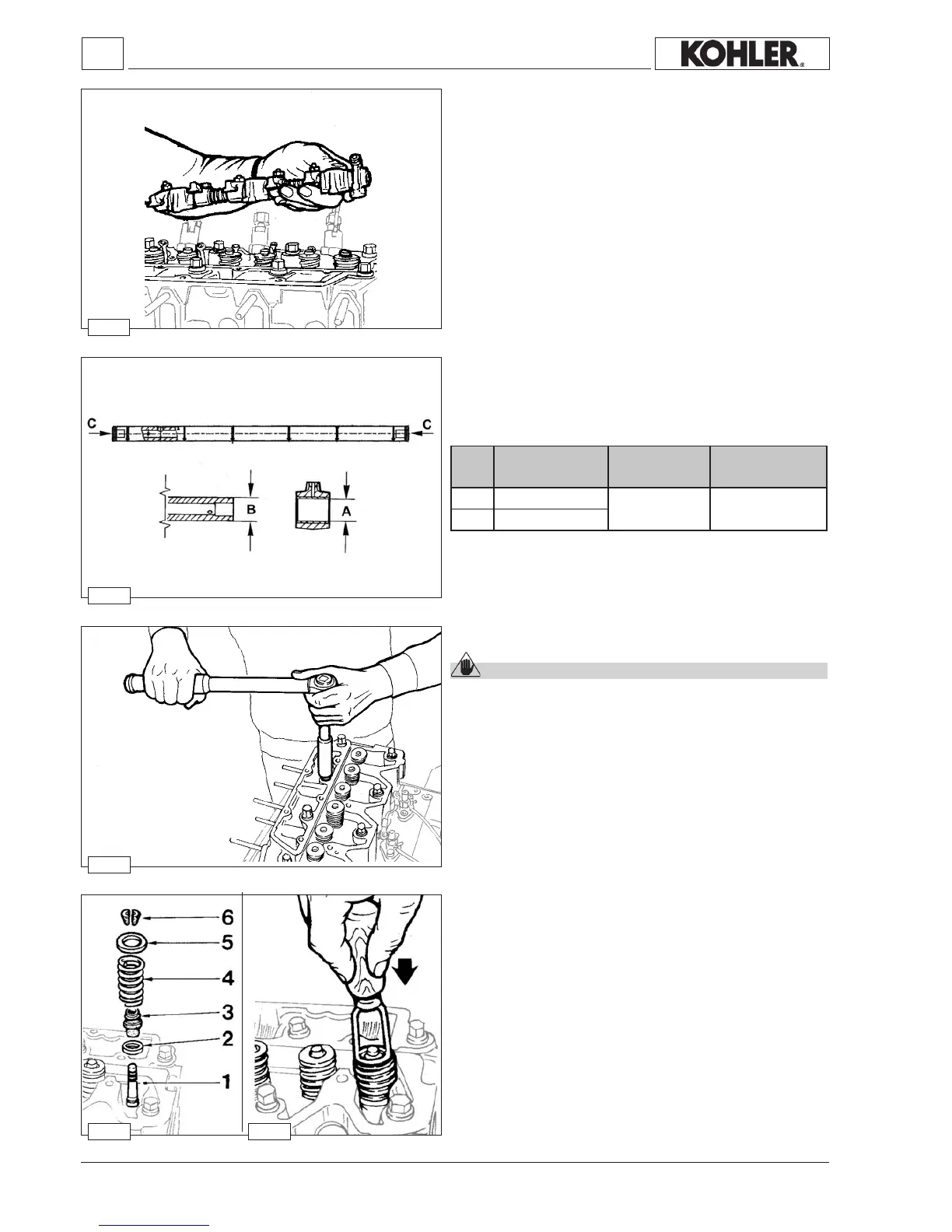
17
16
20
ØA* 14,032÷14,050 ØA-ØB=
0,043÷0,050
0,014
ØB 13,989÷14,000
6
- 40 - - 40 -
Disassembly / Reassembly
Tocheckthepinandtherocker-armpinbearingsforwearcompare
themeasuredvalueswiththeparametersinthetablebelow.
Table of pin-rocker arm dimensions
* Withbushingttedtotherockerarmandreamed.
Clearance
(mm)
Limit value (mm)
Dimensions
(mm)
Ref.
Cylinder head
Caution – Warning
Do not demount when hot or the part could become
deformed.
Donotremovewhenhottoavoiddeformation.
Check cylinder head plane using a metal straight edge and
thickness gauge; if warpage exceeds 0.10 mm, level off by
removingamaximum0.20mm.
See pictures 56÷59 (pages 39÷40) for cylinder head
tightening.
Valve removal
Components:
1
-Valve
2-Lowerspringseat
3-Valveguideseal(forintakeonly)
4-Spring
5-Springcap
6-Cotters
Toremovethecottersrmlypressdownasshowninthegure
20.
Rocker arm assemly
Loosenthescrewswhichfastentheassemblytothehead.
WhenrettingapplyadropofLoctite270ontothethreads.
Whenrettingtightento50Nm.
Insidetherockerarmpinowstheoilthatlubricatestherocker
armsandfeedsthehydraulictappets.
To clean the rocker-arm pin inside, remove the two tightening
screwsC attheends(g.17).
Workshop Manual KDW 1603_2204_2204/T _ cod. ED0053029180 - 1° ed_rev. 00

 Loading...


