EN
UAB AMALVA we reserve the right to make changes without prior notice
30
C5.1-16-03-v1
Personalization
Language
English
Flow units
m
3
/h
Screen saver
On
Panel lock
O
Touch sound
Click
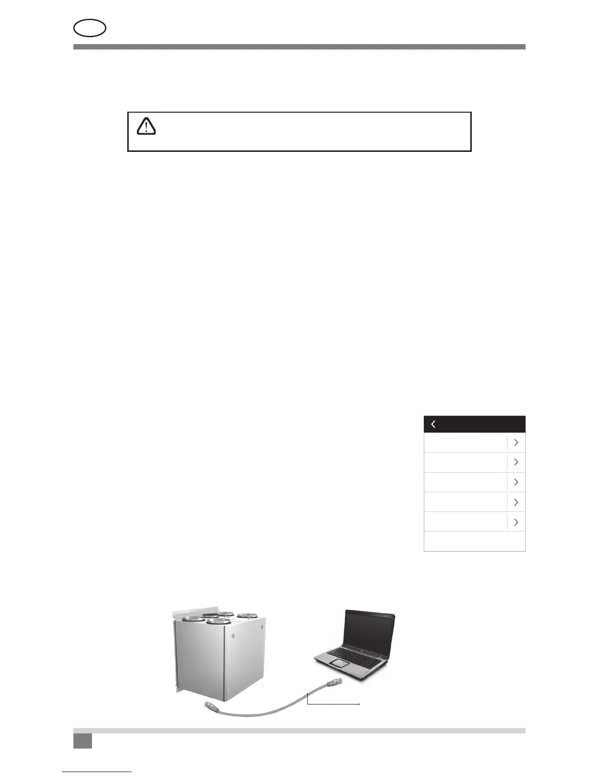
2.6. Control of air handling units through a web browser
You may not only monitor the operation of air handling units and the functionality of their individual components,
change settings and activate extra functions by means of control panel but also by your computer. All you need
is to connect the unit to the computer, local area network or the Internet using a network cable.
Standard CAT 5 network cable
control is performed, while the other air ow (in this case, discharged air) operates as the slave ventilation
system and always follows the master one. If the supply air requirement in the ventilation system which is
assigned as the master system decreases, the intensity of discharged air in the slave system is reduced
correspondingly by the same percentage.
If the variable air volume control function is mode is selected, the initial
calibration of the control mode must be performed; otherwise, the unit
will not operate if the VAV mode is selected.
Variable air volume control mode calibration:
1. Before start of calibration the air distribution and exhaust devices in ventilation system should be adjusted,
all valves for variable air ow in a way enabling air supply to all ventilated premises should be opened.
2. After switch on of the unit the VAV mode should be selected and calibration procedure should be conrmed.
After the end of the calibration, depending on the conguration of pressure sensors, VAV mode status will
change to Supply, Extract, Double.
3. After calibration the air handling unit further will operate in the previous mode.
• DCV– direct controlled volume. The air handling unit will operate similarly as in the CAV mode, but air
volumes will be maintained directly in accordance with the values of the B6 and B7 analog input signals
of controller. After giving the signal 0... 10 V to the appropriate input, it will be converted according to the
current determined air volume. For example, if the maximum air ow of the unit is 1000 m
3
/h, setpoint in the
panel – 800 m
3
/h, and the B6 input value – 7 V, the unit will supply constant air volume of 560 m
3
/h, i. e.,
70 % of the set value. The same applies to the exhaust air only by B7 input.
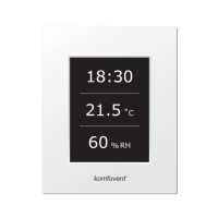
Time / Date
Time and date is required for air handling unit operation planning.
Connectivity
• IP address and subnet mask. Setting is required when air handling unit is connected to PC network or In-
ternet.
• Controller ID. Number that identies the controller, when several air handling units are connected to com-
mon network and controlled by one control panel.
• RS-485. Settings of external RS-485 interface (1, 2, 3 terminals, picture 1.3 b).
2.5.4.2. Personalization
In this item for the user are presented menu language, measurement units and
other control panel settings.
 Loading...