EN
UAB AMALVA we reserve the right to make changes without prior notice
32
C5.1-16-03-v1
The function of step rotation is provided, when capacities of coolers are
the same.
The number of direct evaporation cooling units must be provided in ad-
vance.
2.7.4. Reversal of direct evaporation coolers
There is a reverse option of direct evaporation coolers, i.e. when the cooler is switched to the heating mode. In
such case, there must be only max 3 cooling control steps. There are control terminals DX3 for connection of
the cooler reversing signal “Heating” (Pic. 1.3 b.).
The option of reversal of direct evaporation cooling units must be pro-
vided in advance.
2.8. Troubleshooting
If the unit fails to operate:
• Make sure that the unit is connected to the power supply network.
• Check whether the main switch (if designed) is turned on.
• Check all fuses of the automatics. If necessary, replace blown-out fuses with new ones having the same
electrical parameters (the sizes of the fuses are indicated on the schematic electrical diagram).
• Check whether there is any failure message on the control panel. If there is indication, it needs to be elimi-
nated rst. In order to eliminate the failure, follow the table.
• If nothing is indicated on the control panel, check whether cable connecting control panel with the unit is
not damaged.
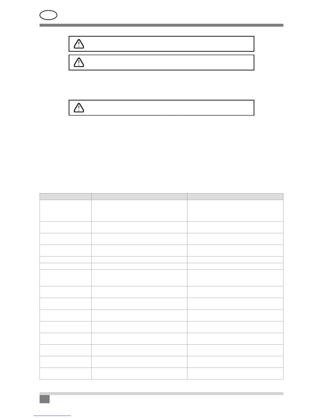
2.8 Table. Alarms indicated on the control panel, their possible causes and elimination methods
Message Possible cause Elimination
Service time
If unit continuous operation (without breaks) was
12 months, then periodic inspection message ap-
pears.
After disconnecting the unit from power supply, it is
necessary to carry out periodic inspection of the unit,
i.e. to check the condition of the heat exchanger, the
heater and fans.
Low supply air ow Too high resistance of the ventilation system.
Check pressure pipes, air dampers, air lters and
make sure that the ventilation system is not blocked.
Low extract air ow Too high resistance of the ventilation system.
Check pressure pipes, air dampers, air lters and
make sure that the ventilation system is not blocked.
VAV calibration fail Pressure sensors are not connected or broken.
Check connections of the sensor or replace the
sensor.
Change outdoor air lter The fresh air lter is blocked. Shut down the unit and replace the lter.
Change extract air lter The extract air lter is blocked. Shut down the unit and replace the lter.
Electric heater off
The heater is disconnected due to too low air vol-
ume.
As soon as the heater cools down, protection re-
sets automatically. It is recommended to increase
the ventilation intensity level.
Service mode
Temporary mode, which can be activated by the
service personnel.
The service mode is switched off by simply delet-
ing the alert message.
Supply air temperature
sensor failure
The supply air temperature sensor is not con-
nected or broken.
Check connections of the sensor or replace the
sensor.
Extract air temperature
sensor failure
The discharged air temperature sensor is not con-
nected or broken.
Check connections of the sensor or replace the
sensor.
Outdoor air temperature
sensor failure
The external air temperature sensor is not con-
nected or broken.
Check connections of the sensor or replace the
sensor.
Exhaust air temperature
sensor failure
The exhaust air temperature sensor is not con-
nected or blocked.
Check connections of the sensor or replace the
sensor.
Water temperature sensor
failure
The water temperature sensor is not connected
or broken.
Check connections of the sensor or replace the
sensor.
Return water temperature
low
Return water temperature of the heater dropped
below the permissible limit.
Check the status and operation of the circulation
pump, heating system and mixing valve actuator.
Internal re alarm Fire danger in the ventilation system.
Check the ventilation system. Find the source of
the heat.
 Loading...