Chapter 2 Disassembly / Reassembly
2-11
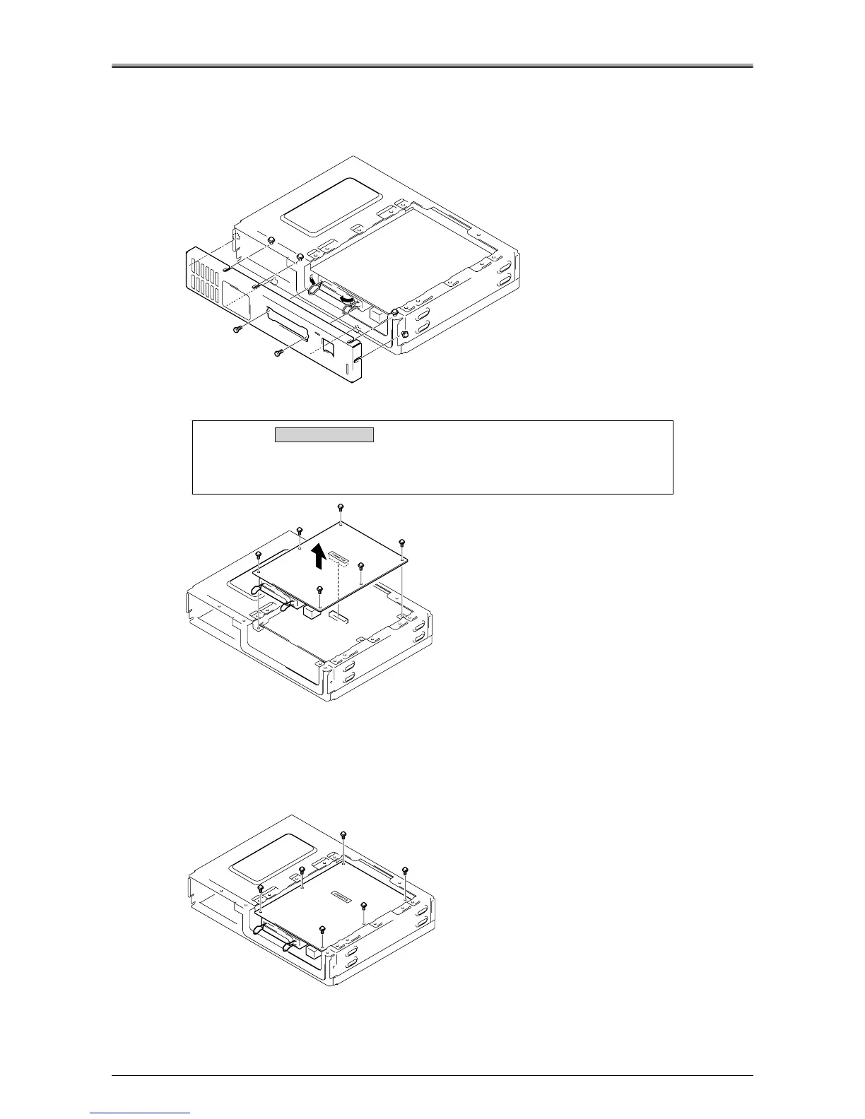
2.
Push the locking levers for the parallel connector to the inside, and remove the 2
screws.
3.
Loosen the 7 screws, then remove board attachment /C.
4.
Remove the 6 screws, then slowly lift out the printer I/F board.
Installation Procedure
1.
Attach the printer I/F board with the 6 screws.
Align the 6 holes on the printer I/F board with the 6 holes on printer controller and place the printer I/F
board on the attachment area, then insert the relay connector into the "CONNECTOR" socket in the
center of the printer I/F board.
2.
For the remaining steps, reverse the procedure for removal.
Caution:
The printer I/F board is connected to the printer controller board by the
connector (CN1) in the center of the board. Be careful not to damage the
connector during removal/installation.
Removal / Installation