Chapter 2 Disassembly / Reassembly
2-10
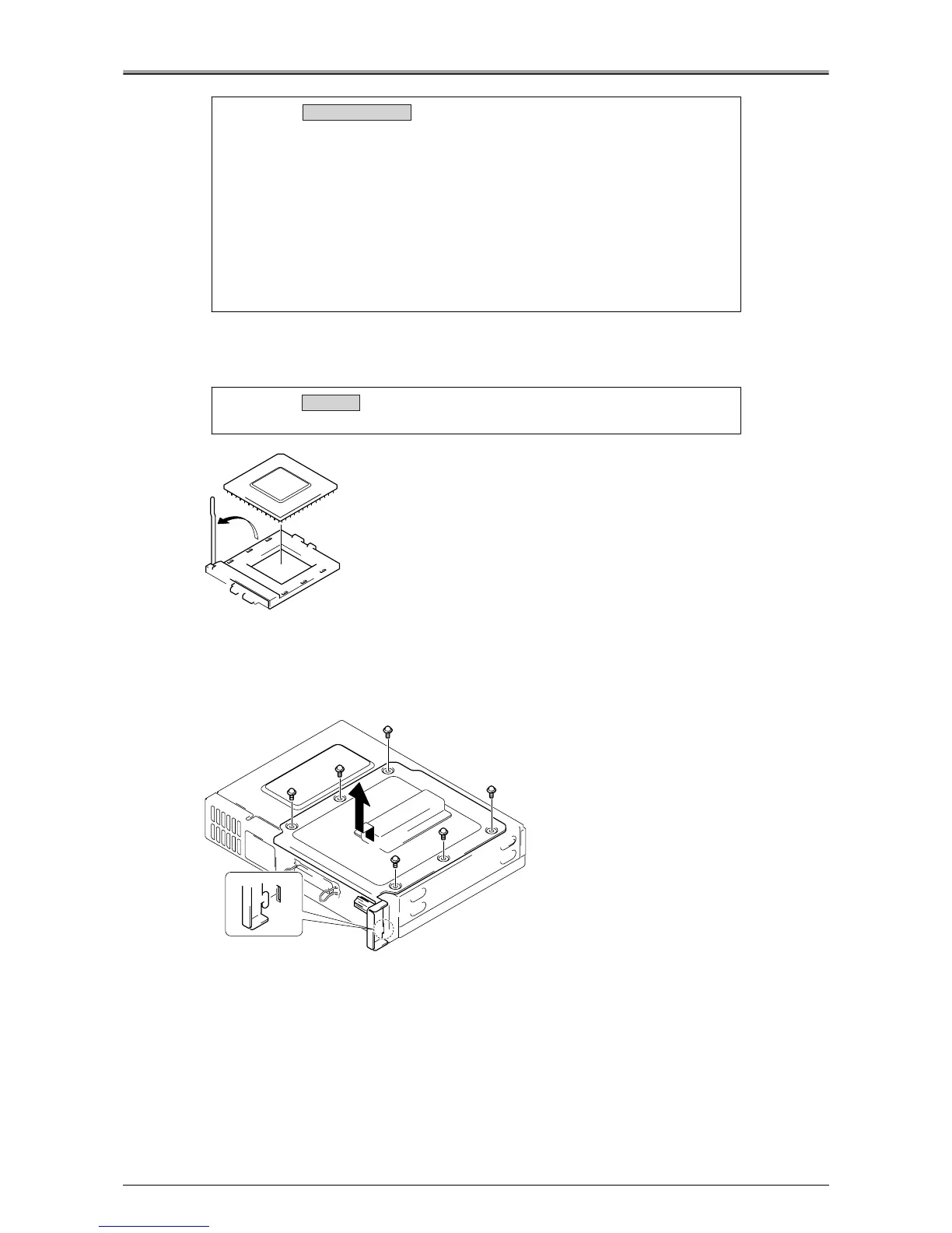
3.
Slowly lift the lever up in the direction of the arrow to release the CPU.
4.
Remove the CPU.
●
Removal / Installation of the Printer I/F Board
Removal Procedure
1.
Remove the 6 screws, then remove the electrical locking plate.
Caution:
• Be careful not to mislay the (2) radiation sheets, 1 each between the
heat sink and CPU and between the heat sink and the North Bridge.
Also be sure to apply the radiation sheet when installing the heat sink.
• There are 2 types of radiation sheet. Be sure to use the correct sheet for
each location.
Radiation sheet for CPU: 30x30x1mm
Radiation sheet for North Bridge: 30x30x2mm
• When installing the radiation sheets, there is sufficient space to install
the sheets then the heat sink. When installing the radiation sheets,
install them so that they face each IC board.
Caution:
Be sure to install the CPU correctly.
Removal / Installation
Installation