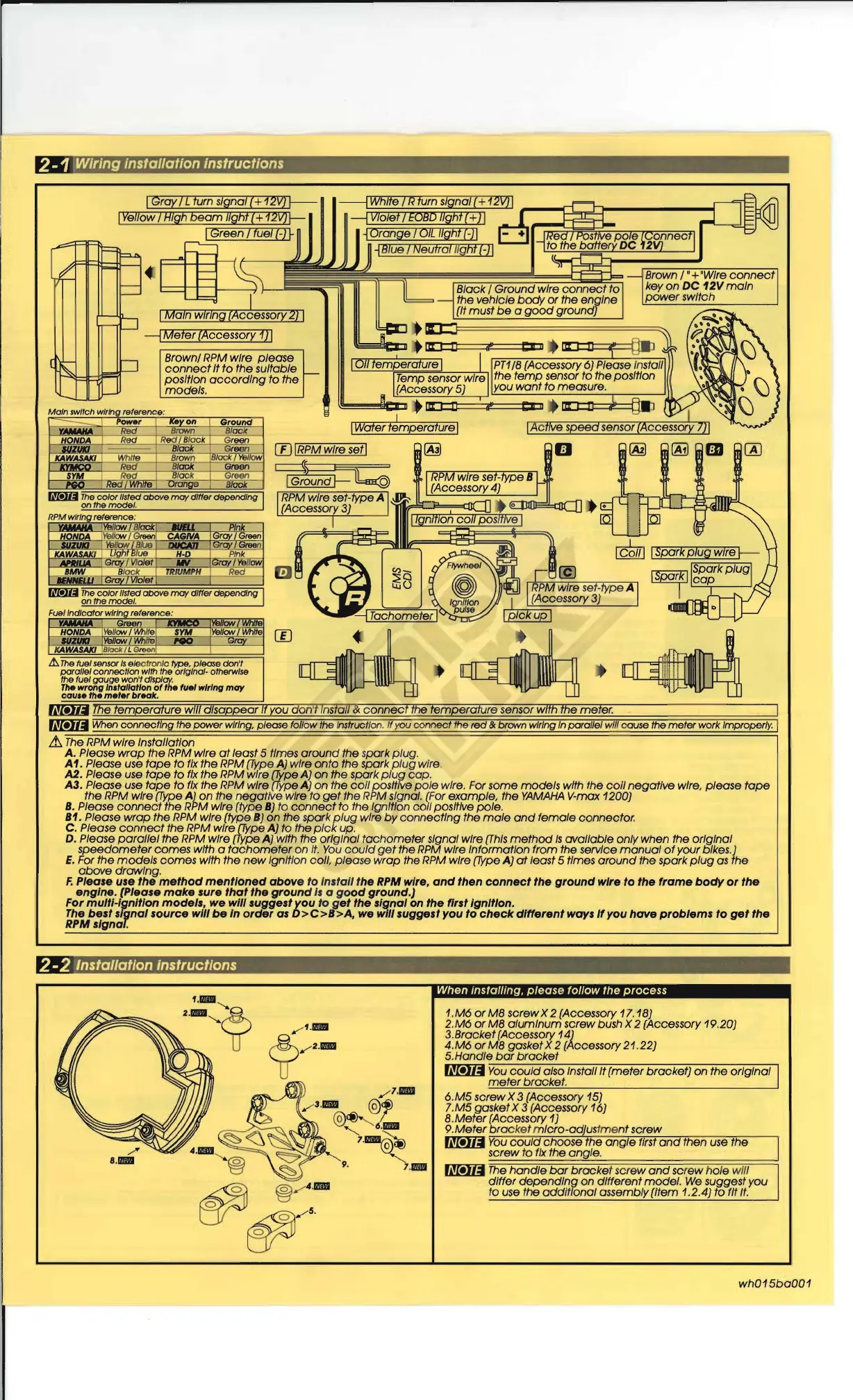
2 -1
Wiring
installation instructions
,.--
r-
r-=
~
r--
(~
.....
f-
~
d
---.J
D
IGray 7Lturn signal
(+
12V)
~
----lWhite 7R turn signal {+
12V]
I
,--...o{::::b...d:::J--------I
---1
Violet 7
EOBD
nght (+ ) I
~
Orange 7
OIL
!Igtlt (-) I
~
Blue 7Neu
fial
l
lg
ht
(-) I
---l
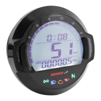
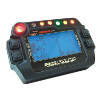
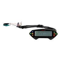
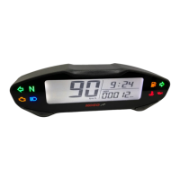
Meter
(Accessory 1) I
Brown/
RPM
wire please
connect
It
to
the suitable
position
according
to the
models.
W I
RPM
wire setl
c:::::::$
fl:::
IGround
f-
l!::m(Q)
~
__
~~
~
~~~~~
~
~~a
Fuel
.1..
The
fUel
sensor
Is
el
ec
tronic
type
. please don't
parallel connect/on
w/tt)
tile original· oftlerwlse
tile
fuel
gauge
won't display.
The
wrong In,'a/kltlon
of'he
fuel
wiring
may
cau
••
the
m.ter
break
.
flMa
The
temperature
wm
disappear
If
you don't Instan &
connect
ffle temperatUre sensor with
the
meter.
U1!Jlj
When connecting the power wiring. please follow the Instruct/on.
"you
connec
t the
red
&
brOlVn
wiring In parallel will cause the
meter
work
Improperly. I
~
The
RPM
wire Instal/atlon
A. Please
wrap
the
RPM
wire
at
least 5 times
around
the spark
plug
.
A1. Please use
tope
to
fix
the
RPM
(Type
A)
wire onto the spark
plug
wire,
A2. Please
use
tope
to
fix
the
RPM
wire (Jype A) on the spark
plug
cop.
A3. Please
use
tope
to
fix
the
RPM
wire
(Type
A) on the
coli
positive
pole
wire. For some models with the
coil
negative wire, please
tope
the
RPM
wire
(Type
A) on the negative wire to
get
the
RPM
signal. (For example, the
YAMAHA
V-max 1200)
B.
Please
connect
the
RPM
wire (type
B)
to
connect
to the Ignition col/ positive pole.
B1.
Please
wrap
the
RPM
wire (type
B)
on the spark
plug
wire
by
connecting the
mole
and
female
connector.
C. Please
connect
the
RPM
wire
(Type
A) to the
pick
up.
D. Please
parallel
the
RPM
wire
(Type
A) with the original
tachometer
signal wire
(This
method
Is
oval/able only when the orIgInal
speedometer
comes with a
tachometer
on
It.
You
could
get
the
RPM
wIre InformatIon from the servIce
manual
of
your bIkes.)
E.
For the
models
comes wIth the
new
IgnItIon
colt
please
wrap
the
RPM
wIre
(Type
A)
at
least 5 tImes
around
the spark
plug
as
the
above
drawIng.
F.
Please use
the
method
mentioned
above
to Install the
RPM
wire,
and
then
connect
the
ground
wire
to
the
frame
body
or
the
engine
. (Please
make
sure
that
the
ground
Is
a
good
ground.)
For multi-Ignition
models,
we will suggest
you
to
get
the signal on the first Ignition.
The
best
signal
source
will
be
In
order
as
D>C>B>A,
we
w111
suggest you
to
check
different
ways
/fyou
have
problems
to
get
the
RPM signal.
2-2 Installation Instructions
When installing,
please
follow the process
1.
M6
or
M8
screw X 2 (Accessory
11.
18)
2.M6
or
M8
alumInum screw bush X 2 (Accessory 19.20)
3. Brocket (Accessory
14}
4.M6
or
M8
gasket X 2 (Accessory 21. 22)
5.Handle
bar
brocket
Ul!llI
You
could
also Install It (meter bracket) on the orIgInal
meter
brocket
.
6.MS screw X 3 (Accessory 15)
7,
M5
gasket X 3 (Accessory 16)
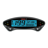
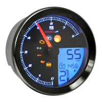
8.
Meter
(Accessory
1)
9,
Meter
bro
cket m
IcrO
-
ad
us
tm
ent screw
U1!Jlj
You
cou d choose the
angle
first
and
then
use
the
screw to
fix
the
angle
.
U1!Jlj
The
handle
bar
brocke
t scr
ew
and
screw hole will
dIffer
dependIng
on dIfferent
model
.
We
suggest you
to use the oddltronal assembly (Item
1.2
.4) to fit
It.
wh015ba001