BA 35203_04 * 3.0 * 35203_04_05_Bedienung.fm 5-57
Operation 5
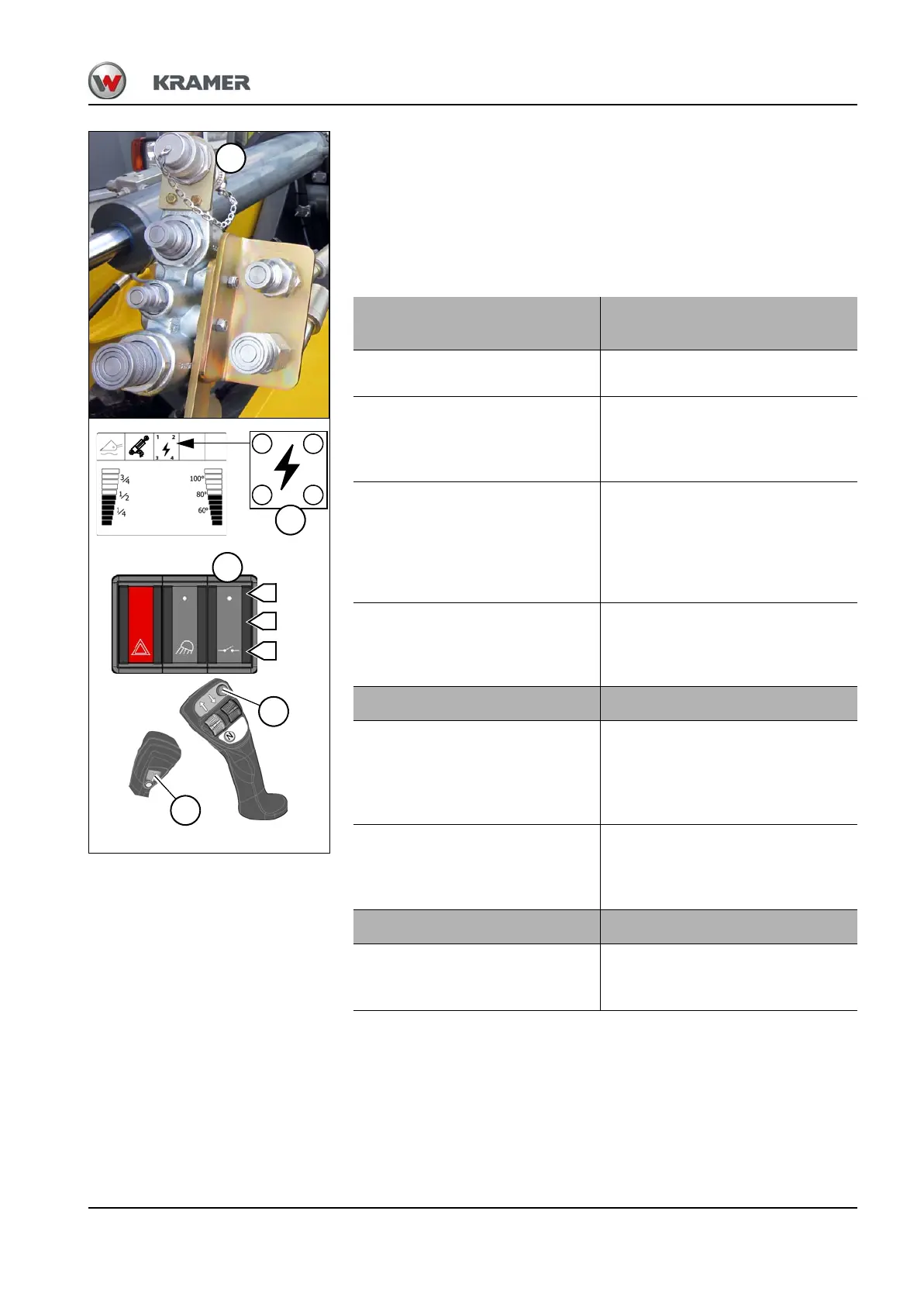
Operation of the 14-pole plug receptacle (A)
• The selection and activation of the first 3 control circuits P/1, 2 or 3
occurs via the toggle switch and touch button 43.
• The selected electrical circuit is operated via the toggle switch 82 on
the joystick.
• The operation of the 4th control circuit P/4 occurs with the touch
button 85 on the joystick and can be used in parallel to the other
control circuits.
Operation of
electrical circuit 1, 2 or 3
Function
1. Establish the electric
connections to the attachment.
➥ Plug – plug receptacle
2. Put switch 43 in the middle
position B.
➥ The LED in the
switch illuminates.
➥ Operation of the 3rd hydraulic
control circuit is disabled.
3. Select electrical circuit. To do
so, press the touch button 43
briefly in position C until the
required electrical circuit is
indicated in digital display with
the symbol P/1, 2 or 3.
➥ The selected electrical circuit is
activated.
4. Press and hold switch 82 on the
joystick to the left or right.
➥ Operation of active electrical
circuit (for example for controlling
different electro-hydraulic control
valves).
Operation of electrical circuit 4 Function
5. Press the touch button 85 on
the joystick briefly ON.
➥ Continuous operation for
electrical functions (e.g. electric
water pump on sweeper).
➥ Symbol P/4 lights up in the digital
display.
6. Briefly press touch button 85
repeatedly: OFF.
➥ Symbol P/ 4 goes out in the
digital display.
➥ Continuous operation for
electrical functions is disabled.
Disabling all electrical circuits Function
1. Press push button 43 to
position A.
➥ All electrical circuits are disabled.
➥ Operation of the 3rd hydraulic
control circuit is enabled.