KRAMER: SIMPLE CREATIVE TECHNOLOGY
Installing the Balanced Stereo Audio Matrix Switcher
16
Refer to section 6.6 for details of how to set the DIP-switches, and to
section
6.7 for details of how to control this group of interconnected
varied-format 16x16 series switchers, and other configurations.
6.6 Setting the DIP-switches
Configure the VS-1616A by setting the 8 DIP-switches as
Figure 12 and
Table 4 define:
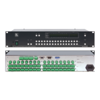
Figure 12: Rear Panel DIP-switches
Table 4: DIP-Switch Definitions
1-4 Set the MACHINE # (see Table 5 in section 6.6.1)
5 Enables (ON) or disables (OFF) the Follow-SYSTEM mode
6 Enables (ON) or disables (OFF) the SLAVE mode in a multi-channel configuration
7 Disables use of a null modem adapter
OFF = RS-232 connection via a null modem adapter
ON = RS-232 connection without a null modem adapter
with RS-232
8 RS-485 termination for first and last machine = ON (RS-485 line terminates with
110Ω); for others = OFF (RS-485 line is open)
6.6.1 Setting the MACHINE #
To control a unit via RS-232 or RS-485, each unit has to be identified via
its unique MACHINE #. In an extended matrix configuration, in addition
to the MACHINE #, each unit is identified via its MACHINE ADDRESS
#.
Set the MACHINE #
2
Table 5 on a VS-1616A unit according to .
A valid MACHINE # is from 1 to 15.
1 See section 6.7.1
2 When using a single unit, set the unit to MACHINE # 1