Your Balanced Stereo Audio Matrix Switcher
5
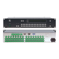
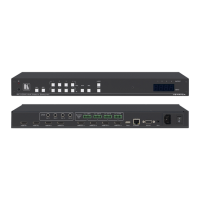
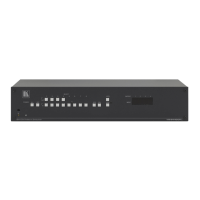
Table 1: Front Panel VS-1616A Features
1 IR Receiver The red LED is illuminated when receiving signals from the Kramer
Infra-red remote control transmitter
2 Power Switch Illuminated switch supplying power to the unit
3 ALL Button Pressing ALL followed by an INPUT button, connects that input to all
outputs
4 OFF Button An OFF-OUT combination disconnects that output from the inputs; an
OFF-ALL combination disconnects all the outputs
5 IN Buttons Select the input to switch to the output
6 OUT Buttons Select the output to which the input is switched
7 STO Button Stores the current setting in the non-volatile memory
8 RCL Button Recalls a setup from the non-volatile memory
9 LCD MATRIX Display
1
Displays the selected input(s) switched to the output(s) (above or below
the corresponding OUTPUT label) and user interface messages
10 LCD STATUS Display
Displays the matrix status
11 MENU Button Selects the programming commands to setup the switcher
12 TAKE LED Shows the current TAKE button mode aiding the completion of actions
13 TAKE Button Used to confirm and complete setup and switching
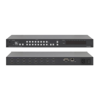
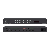
Table 2: Rear Panel VS-1616A Features
14 IN Terminal Block Connectors Connect to the audio sources
15 OUT Terminal Block Connectors Connect to the balanced audio acceptors
16 EXTENSION / UNBALANCED OUT
Terminal Block Connectors
Connect to the EXTENSION / UNBALANCED OUT
terminal block connectors on another unit, and/or to the
unbalanced audio acceptors
17 SYNC (IN and OUT) BNC Connectors Connect to daisy-chained video units for AFV setting
18 EXT. (extension) KEYS Terminal Block
Connectors
Connects to an external keyboard (remote unit)
19 RS-485 Terminal Block Port Pins # 1 and # 2 are for vertical sync and Ground
connection, and Pins # 3 and # 4 are for RS-485
20 RS-232 IN 9-pin D-sub (F) Port Connects to the PC or the Remote Controller
21
RS-232 OUT 9-pin D-sub (M) Port Connects to the RS-232 IN 9-pin D-
unit in the daisy-chain connection
22 SETUP DIP-switches DIP-switches for setup of the unit
23 REMOTE IR 3.5mm Mini Jack Connect to an external IR receiver unit for controlling the
machine via an IR remote controller (instead of using the front
panel IR receiver)
3
24
Power Connector with Fuse AC connector enabling power supply to the unit
1 In sections 7.2.4 and 8, the word “Displays” refers to the LCD MATRIX and STATUS Displays
2 If the unit is not the first unit in the line, connects to the RS-232 OUT 9-pin D-sub (F) port of the previous unit in the line
3 Optional. Can be used instead of the front panel (built-in) IR receiver to remotely control the VS-1616A (only if the internal
IR connection cable has been installed)