Refer to section 8.2 for a description of the MENU’s Follow-SYSTEM
and Breakaway-from- SYSTEM modes.
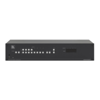
6.6.4 Understanding the SLAVE Mode
The SLAVE mode is only used for the multi-channel audio switcher
configuration
2
Figure 6
, for example, when using 2 VS-1616A units to form a
4-channel 16x16 configuration, as illustrates.
One unit is used as the Master, and the other unit is a Slave. The Slave
always follows the Master. In the example illustrated in
Figure 6, the first
VS-1616A unit is the Master (with DIP 6 set OFF disabling the Slave
mode) and the second VS-1616A unit is a Slave (with DIP 6 set ON
enabling the Slave mode).
On the Slave VS-1616A unit, the MATRIX and STATUS Displays do
not illuminate and the STATUS Display shows the following message:
Keyboard LOCKED
However, the STATUS Display on the Slave VS-1616A unit dynamically
shows
3
Front panel control is via the Master VS-1616A unit, on which the front
panel buttons are unlocked and both the MATRIX and STATUS Displays
illuminate.
all changes made from the Master VS-1616A unit.
6.7 Connecting a Control Interface
Connect a control interface (RS-232 or RS-485) unless operating a
VS-1616A as a standalone unit without any control device (that is, with
control from the front panel or IR port, and not via a remote controller or
a PC). The control interface must be identical on each switcher in the
series of 16x16 matrix switchers; either RS-232 or RS-485. One control
interface suffices. Do not use both RS-232 and RS-485 control interfaces
in the same configuration. For example, in an interconnected varied-
format 16x16 switcher application
4
1 See section
, if the switcher that connects to the
PC connects via the RS-232 control interface, each switcher must
interconnect via the RS-232 control interface and not via the RS-485
control interface.
6.5
2 See section
6.1
3 Albeit with an LCD Display that does not illuminate
4 See section
6.5