33
6.5. Electrical connections
All electrical connections must be made after the power supply is cut off and with any potential emergency battery disconnected.
To connect an external control, safety and signalling device, use openings provided for this purpose (sealed with gaskets) in the control
unit housing.
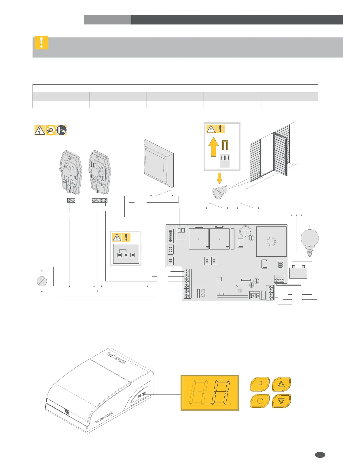
Install the electrical connections according to the diagram shown in the figure below.
After installation, make sure that electrical wires do not touch the moving parts of the garage door.
Check the status of inputs and make sure that all safety devices are properly connected.
Program the drive using the control panel (see sec. 7):
IMPORTANT! Before starting any work on the control panel
(connection, maintenance), always cut off the power supply.
Wiring diagram of the control board
1 2 3 4 5
Pulse switch Photocells Lamp Reed switch / STOP Emergency battery
EN
-
+
4 FLASH
2 PB
3 PE
+24V DC
STOP
ANT
6 BAT
24V/2.4Ah
+-
COM
-
+
OUT
GND
FLASH
NC
5 DOOR
RXTX
NC
STOP
GND
GND
PB
NO
NC/NO
NC
NO
MAX
5OOW
COM
NO
NC
L
230V AC
N PE
 Loading...