5 Installation/ Commissioning
22 of 50
KSB Guard
4079.83/01-EN
NOTE
The LTE antenna is the larger of the two antennas. The sensor network antenna is
noticeably shorter and slightly thicker.
ü The signal strength of the mobile network at the place of installation of
KSBGuardGateway is sufficient.
1. Screw the sensor network antenna to the connection on the left-hand side.
2. Screw the LTE antenna to the connection on the right-hand side.
NOTE
If the signal strength of the mobile network at the place of installation of
KSBGuardGateway is insufficient, the LTE antenna can be fitted in a more suitable
place, using the mounting angle provided. In this case, the antenna has to be
connected to KSBGuardGateway with a commercially available antenna extension
cable with TypeN connector. The maximum permissible length of the antenna
extension cable is 20m.
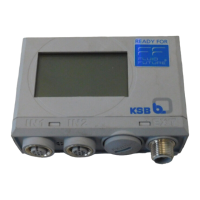
5.2.1.5 Checking the signal strength of KSBGuardGateway
▪ Minimum sufficient signal strength is indicated by 2level LEDs lighting up.
▪ Good signal strength is indicated by 3level LEDs lighting up.
▪ Maximum signal strength is indicated by 4level LEDs lighting up.
1. Check the level LEDs for mobile network signal strength.
2. If necessary, change the position of the sensor network antenna. Check the
signal strength again. If the signal strength is sufficient, fasten the antenna in
this position with a mounting angle.
The antenna cable should not exceed 20 m in length.
NOTE
The KSBGuardGateway antenna acts in the plane perpendicular to the antenna’s
axis. The transmission and battery unit should be approximately in the same plane
as the antenna.
5.2.1.6 Commissioning KSBGuardGateway
The device is delivered fully configured and is ready for operation after the power
supply has been connected. The current operating status is indicated by the LED for
the supply voltage.
After KSBGuardGateway has been energised, observe the LEDS1 at
KSBGuardGateway. The following operating statuses may occur:
▪ LED S1 green, flashing evenly
Firmware update running automatically, duration approx. 10 to 15min.
▪ LED S1 green, permanently lit
Device ready for operation.
5.2.2 Positioning the transmission and battery unit
Set-up mode The Set-up mode helps find a suitable position for the Transmission and battery unit.