5 Installation/ Commissioning
26 of 50
KSB Guard
4079.83/01-EN
8. Check that the sensor unit is firmly positioned on the bearing bracket or drive
lantern; re-glue the sensor unit if necessary.
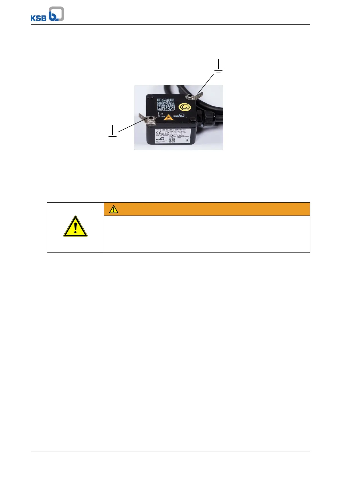
Fig.13: Earthing connections of the sensor unit
9. Connect both earthing connections to an earthing point in the system with a
suitable cable and the supplied flat connector, type: TE 2178301-1 (cable cross-
section 4mm²) (ðFig.13) .
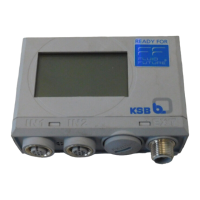
5.2.6 Installing the transmission and battery unit
WARNING
Work in the immediate vicinity of rotating parts
Risk of hand injury!
▷ Always have this work performed by trained personnel.
▷ Take particular caution when performing this work.
The area selected should have the following properties:
▪ Ambient temperature ≤70°C
▪ Position protected
▪ Level
▪ Maximum distance from the floor 2m
ü The electrical connection between the sensor unit and the Transmission and
battery unit has been established.
ü The batteries have been inserted (as-supplied condition).
ü The signal strength of the KSBGuardGateway connection at the place of
installation is sufficient.
ü Check the signal strength of the connection to the Transmission and battery unit
in Set-up mode.
1. Preferably position the Transmission and battery unit in such a way that a line of
sight is provided to KSBGuardGateway. In the process, ensure that the
connecting point of the connecting cable can be easily accessed.
2. Clean the surface of the Transmission and battery unit and the surface of the
place of installation using the supplied alcohol pads.
3. Securely attach the Transmission and battery unit with the supplied fastening
material.