7 Servicing/Maintenance
62 of 80
HPK
1121.8/06-EN
7.5.3.2 Packing the gland
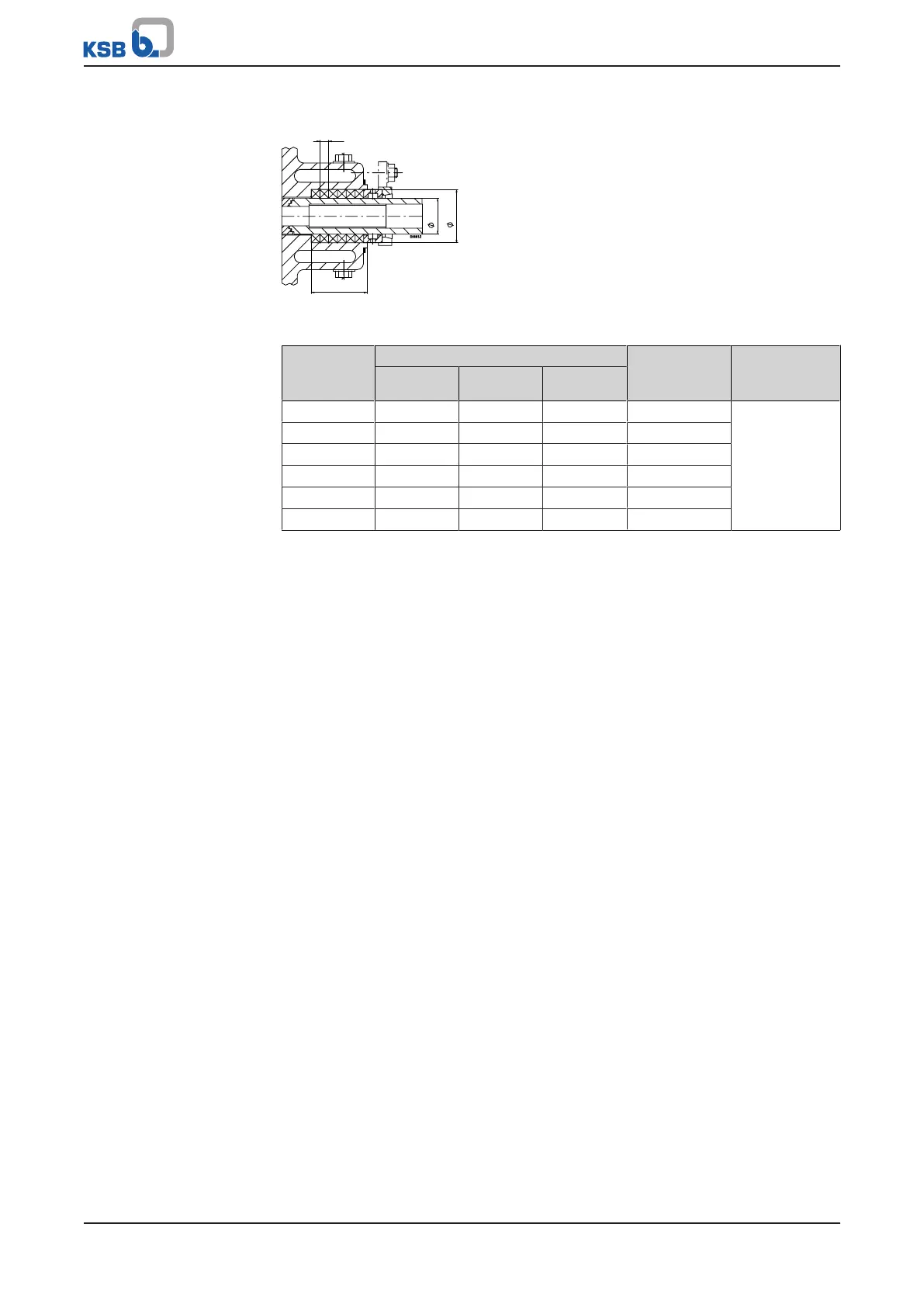
Fig.18: Gland packing chamber
Table25: Gland packing chamber
Bearing
bracket
Gland packing chamber
Packing
cross-
section
Packing
rings
Ø d
1
Ø d
2
l
P02as 35 51 53 8 x 8 4 rings and
a second
stuffing box
ring
or
6 rings
P03s, P03as 45 65 64 10 x 10
P04s, P04as 55 75 64 10 x 10
P05s, P05as 70 95 79 12,5 x 12,5
P06s, P06as 80 105 79 12,5 x 12,5
P08s 100 132 102 16 x 16
Pure graphite packings see supplementary operating instructions.
Always use pre-compressed packing rings.
ü The information and steps stated in (ðSection7.5.1,Page59) to
(ðSection7.5.2,Page60) have been observed/carried out.
ü The pre-assembled bearing assembly as well as the individual parts are kept in a
clean and level assembly area.
ü All disassembled parts have been cleaned and checked for wear.
ü Any damaged or worn parts have been replaced by original spare parts.
ü The sealing surfaces have been cleaned.
1. Clamp casing cover 161 into a vice.
2. Push in neck bush 456.01.
3. Insert the first packing ring, ensuring that its cut edge is in horizontal position.
4. Hold the packing ring in place and slide shaft protecting sleeve 524 (chamfered
side first) into the gland packing chamber from the pump end.
5. Slightly expand the inside diameter of the packing ring by moving shaft
protecting sleeve 524 back and forth. Then pull out the shaft protecting sleeve.
Insert each subsequent packing ring separately with its joint offset by approx.
90° in relation to the previous one. Repeat the expansion procedure.
After the last packing ring has been inserted, shaft protecting sleeve 524
remains in the packing chamber.
6. Insert stuffing box ring 454.01 with the drilled hole pointing downwards.
7. Fit gland follower 452 and lightly fasten it by hand with the two hexagon nuts
920.02; make sure to fit discs 550.01.
8. Fit guard 680.
9. Install complete discharge cover 161 with shaft protecting sleeve 524 in the
pump; take care not to damage joint ring 411.11.
 Loading...


