7 Servicing/Maintenance
66 of 80
HPK
1121.8/06-EN
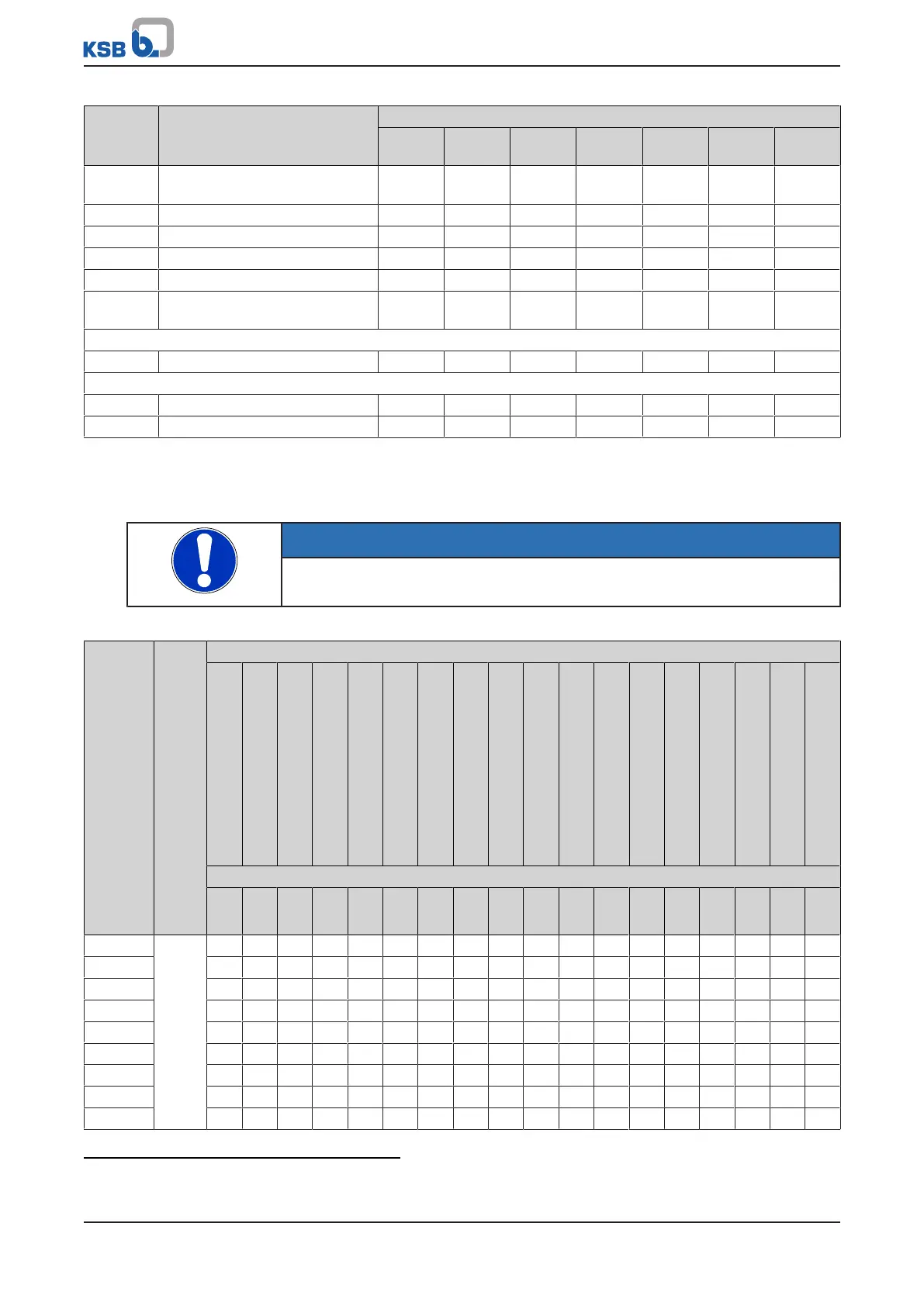
Part No. Description Number of pumps (including stand-by pumps)
2 3 4 5 6 and 7 8 and 9 10 and
more
320.02 Angular contact ball bearing
(set)
1 1 2 2 2 3 25 %
322.01 Cylindrical roller bearing 1 1 2 2 2 3 25 %
502.01 Casing wear ring 2 2 2 3 3 4 50 %
524.01 Shaft protecting sleeve 2 2 2 3 3 4 50 %
- Gaskets for pump casing (set) 4 6 8 8 9 12 150 %
- Torque-transmitting coupling
elements (set)
1 1 2 2 3 4 30 %
For variants with mechanical seal:
433 Mechanical seal complete 1 1 2 2 2 3 25 %
For variants with gland packing:
456.01 Neck bush 1 1 2 2 2 3 30 %
461.01 Gland packing (set) 4 4 6 6 6 8 100 %
7.7.3 Interchangeability of pump components
Components featuring the same number in a column are interchangeable.
NOTE
Volute casing 102 and impeller 230 are not interchangeable between different
pump sizes.
Table30: Interchangeability of pump components
Size
Bearing bracket
Description
Casing cover
Support foot
Shaft
16)
Angular contact ball bearing
17)
Deep groove ball bearing
16)
Cylindrical roller bearing
16)
Bearing bracket
16)
Bearing bracket lantern
Gland follower
Stuffing box ring
Lantern ring
Gland packing
Drip plate
Casing wear ring
Thrower
Shaft protecting sleeve
Guard
Impeller nut
Part. No.
161
183
210
320.02
321.02
322.01
330
344
452.01
454.01
458.01
461.01
463.01
502.01
507.01
524.01
680
922
25-160 P02as 2 2 1 1 1 1 1 2 1 1 1 1 1 25 1 1 1 1
25-200 3 3 1 1 1 1 1 3 1 1 1 1 1 25 1 1 1 1
32-125 1 1 1 1 1 1 1 1 1 1 1 1 1 1 1 1 1 1
32-160 2 2 1 1 1 1 1 2 1 1 1 1 1 1 1 1 1 1
40-160 2 2 1 1 1 1 1 2 1 1 1 1 1 2 1 1 1 1
50-160 2 3 1 1 1 1 1 2 1 1 1 1 1 3 1 1 1 1
32-200 3 3 1 1 1 1 1 3 1 1 1 1 1 1 1 1 1 1
40-200 3 3 1 1 1 1 1 3 1 1 1 1 1 2 1 1 1 1
50-200 3 3 1 1 1 1 1 3 1 1 1 1 1 3 1 1 1 1
16
For identical bearing designs only
17
For bearing brackets P..as and s
 Loading...


