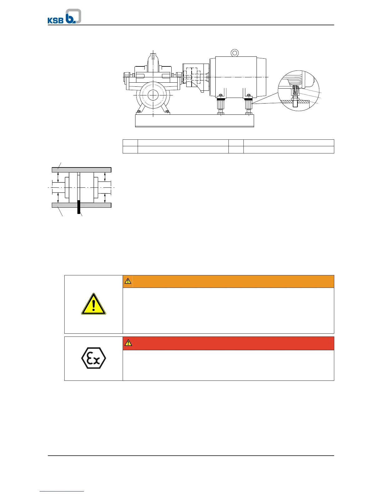
Fig. 14:
Aligning the motor with adjusting screws
1
Hexagon head bolt 2 Adjusting screw
3 Locknut
✓ The coupling guard and the footboard for the coupling guard, if any, have
been removed.
1. Place the straight-edge (c) axially on both coupling halves.
2. Leave the straight-edge (c) in this position and turn the coupling by hand.
⇨ The coupling is correctly aligned if the distances A and B to the respective
shafts are the same at all points around the circumference. The radial and
axial deviation of the two coupling halves must not exceed 0.05 mm. Observe
the coupling manufacturer's operating instructions!
3. Unscrew the hexagon head bolts (1) at the motor and the locknuts (3) at the
baseplate.
4. Turn the adjusting screws (2) by hand or by means of an open-end wrench until
the coupling alignment is correct and all motor feet rest squarely on the
baseplate.
5. Re-tighten the hexagon head bolts (1) at the motor and the locknuts (3) at the
baseplate.
6. Check that coupling/shaft can easily be rotated by hand.
WARNING
Unprotected rotating coupling
Risk of injury by rotating shafts!
▷ Always operate the pump set with a coupling guard.
If the customer specifically requests not to include a coupling guard in KSB's
delivery, then the operator must supply one!
▷ Observe all relevant regulations for selecting a coupling guard.
DANGER
Risk of ignition by frictional sparks
Explosion hazard!
▷ Choose a coupling guard material that is non-sparking in the event of
mechanical contact (see DIN EN 13463-1).
7. Re-install the coupling guard and the footboard for the coupling guard, if any.
8. Check the distance between coupling and coupling guard.
The coupling guard must not touch the coupling.

 Loading...


