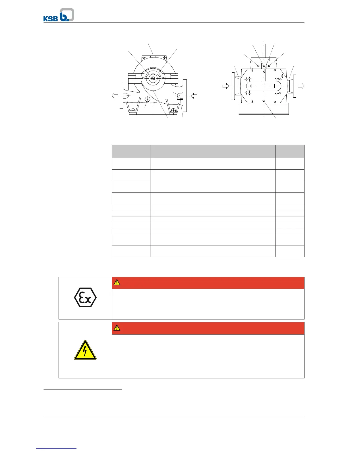
Fig. 19: Auxiliary connections
Table 11: Auxiliary connections
Connection
Description Type of
connection
1M.1 Connection for pressure measurement on
the suction side
G 1/2
1M.2 Connection for pressure measurement on
the discharge side
G 1/2
4M.1 Connection for temperature measurement
at the drive end
G 3/8
4M.2 Connection for temperature measurement
at the non-drive end
G 3/8
6B Connection for pump drain on the suction side G 1/2
6B.1
9)
Connection for pump drain on the suction side G 1/2
6B.2 Connection for pump drain on the discharge side G 1/2
6D Connection for venting the pump G 1/2
8A Connection for leakage drain G 3/4
26M.1 Connection for vibration measurement
at the drive end
M8
26M.2 Connection for vibration measurement
at the non-drive end
M8
5.9 Connection to power supply
DANGER
Incorrect electrical installation
Explosion hazard!
▷ For electrical installation, also observe the requirements of IEC 60079-14.
▷ Always use a motor protection switch for explosion-proof motors.
DANGER
Electrical connection work by unqualified personnel
Danger of death from electric shock!
▷ Always have the electrical connections installed by a trained and qualified
electrician.
▷ Observe regulations IEC 60364 and, for explosion-proof models, EN 60079.
▷ Observe the motor manufacturer's operating instructions.
9)
Applies to sizes 100 - 375, 150 - 290, 150 - 360, 150 - 605, 200 - 420, 200 - 520, 200 - 670, 250 - 600, 250 - 800, 300 - 300, 300
- 435, 300 - 560, 300 - 700, 300 - 860, 350 - 360, 350 - 430, 350 - 510
5 Installation at Site
Omega / Omega V
37 of 94

 Loading...


