Replacing foldable push handles
Diculty:
Tools:
H
ole
p
unch
p
liers
6
mm,
à 3, 4
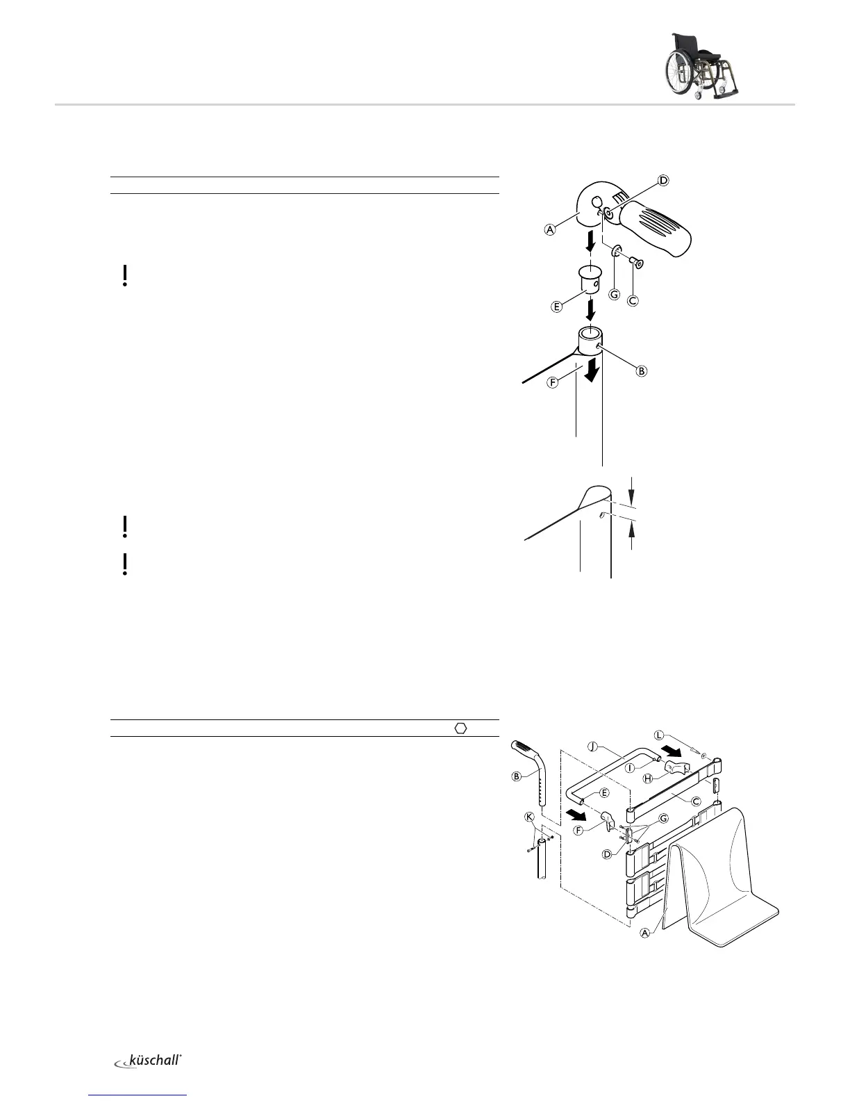
Remove the old foldable push handle.
Pull down the backrest cover F on the telescopic tube, until its
hole B is uncovered.
IMPORTANT!
Make sure that the threaded insert E (part no. 1580450) supplied
with the new push handle is used for assembly.
Place the threaded insert E in the telescopic tube.
Punch a hole through the backrest cover with a distance of
10 mm from the upper egde, using hole punch pliers (see graphic
below).
Slide the new foldable push handle A onto the telescopic tube.
Pull up the backrest cover, until it covers completely the rear hole
in the pushhandle.
Fix the foldable push handle with screw C and washer G.
Check screws D on both sides of the push handle and re-tighten
if necessary.
Carry out the same steps for the other push handle.
IMPORTANT!
Make sure that the folding force is approximately 5 N (0.5 kg).
IMPORTANT!
Fixing screw C may only be used once. Alternatively the screw can
be cleaned (remove old thread locking adhesive) and reinstalled
with new low-strength thread locking adhesive.
i
The retrofit of foldable push handles requires new tubing.
Stabilisation bar
Stabilisation bar assembly
Diculty:
Tools:
Ã3 8 Ò
2
With a back height RH405 or larger it is possible to assemble a stabili-
sation bar to increase the rigidity of the backrest handles.
Remove backrest cover A, push handles B and 10 cm backrest
band (or end band, if no push handles are assembled).
Assemble a 5 cm backrest band C or end band with the screws L
to the push handles B.
Assemble the push handles B with bolts and nuts K.
Attach the clamps D together with the RH socket F and the LH
socket H with the screws G below the backrest band C to the
push handles B.
Replace the push handle/backrest band/socket assembly.
Press pin E and slide the stabilisation bar J into the RH socket F
then swing the stabilisation bar upwards, press pin I and click the
stabilisation bar into the LH socket H.
C à 7 Nm (low-strength)
G à 4 Nm
K à 7 Nm
L à 4 Nm