Do you have a question about the KYMCO DINK50 and is the answer not in the manual?
| Fuel System | Carburetor |
|---|---|
| Front Brake | Disc |
| Rear Brake | Drum |
| Tires Front | 120/70-12 |
| Tires Rear | 130/70-12 |
| Seat Height | 780 mm |
| Transmission | CVT Automatic |
Identifies the engine by its unique serial number.
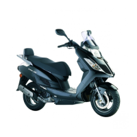
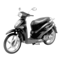
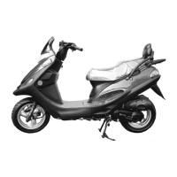
Details technical specifications of the motorcycle model.
Outlines essential safety and handling precautions for servicing.
Lists specified torque values for critical fasteners.
Lists specialized tools required for maintenance and repair.
Illustrates and lists lubrication points on the motorcycle.
Provides a visual schematic of the motorcycle's electrical system.
Offers guidance for diagnosing and resolving common engine performance issues.
Exploded view illustrating exhaust and frame cover components.
Provides general instructions and torque values for exhaust and covers.
Lists common issues related to exhaust mufflers and their probable causes.
Step-by-step guide for removing various frame body covers.
Detailed procedure for removing the exhaust muffler.
Schedule detailing periodic checks and maintenance intervals.
Procedures for inspecting and adjusting the front and rear brake systems.
Inspection and adjustment guidelines for tires and wheel rims.
Inspection procedures for shock absorbers.
Inspection of the transmission case and oil level.
Inspection of ignition apparatus, spark plugs, and timing.
Procedures for adjusting idle speed and inspecting the air cleaner.
Covers adjustments for throttle grip free play and headlight beam.
General instructions and specifications for the lubrication system.
Identifies common problems and their causes within the lubrication system.
Step-by-step instructions for removing the oil pump.
Guidelines for inspecting the oil pump for wear and damage.
Procedures for installing the oil pump correctly.
Process for bleeding air from the oil pump and lines.
Procedure for removing and installing the oil tank.
General instructions and torque values related to engine servicing.
Detailed steps for safely removing the engine from the frame.
Procedures for reinstalling the engine and performing post-installation checks.
General instructions for servicing cylinder head, cylinder, and piston.
Common problems and solutions for compression and piston issues.
Procedures for removing, inspecting, and installing the cylinder head.
Steps for removing, inspecting, and installing the cylinder and piston.
General instructions and specifications for the drive belt and pulley system.
Common issues with the drive belt, pulleys, and clutch.
Procedures for removing, inspecting, and installing the kick starter mechanism.
Steps for inspecting, replacing, and installing the drive belt.
Instructions for removing, inspecting, and installing the drive pulley.
Procedures for removing, inspecting, and installing the starter pinion.
Steps for removing, disassembling, inspecting, and installing the clutch/driven pulley.
Specified oil, disassembly, and change quantities for final reduction.
Common problems related to transmission and gears in the final reduction.
Detailed steps for disassembling the final reduction unit.
Guidelines for inspecting gears, bearings, and seals of the final reduction.
Procedures for assembling the final reduction unit.
General instructions and torque value for A.C. generator servicing.
Step-by-step guide for removing the A.C. generator components.
Procedures for installing the A.C. generator and related parts.
General instructions and specifications for crankcase and crankshaft servicing.
Common issues related to abnormal engine noise from bearings.
Procedure for separating the crankcase halves.
Steps for removing the crankshaft from the crankcase.
Methods for measuring clearances and runout of the crankshaft.
Procedures for installing the crankshaft and bearings.
Steps for assembling the crankcase halves.
Diagram illustrating the components of the cooling system.
General instructions and special tools for cooling system maintenance.
Common problems related to engine temperature and coolant leaks.
Procedures for testing the radiator cap and system for leaks.
Steps for inspecting, removing, and installing the radiator.
Inspection, removal, and replacement of the water pump seal and impeller.
Procedures for removing, inspecting, and installing the thermosensor.
Steps for removing, inspecting, and installing the thermostat.
General instructions, specifications, and special tools for carburetor service.
Common issues with engine starting, idling, and mixture.
Procedures for disassembling and installing the throttle valve.
Steps for removing the carburetor from the engine.
Inspection, removal, and installation of the auto bystarter component.
Procedures for removing, inspecting, and assembling the float chamber.
Steps for installing the carburetor and performing adjustments.
Method for adjusting the air screw for optimal engine performance.
Procedures for removing, inspecting, and installing the reed valve.
Steps for removing, disassembling, inspecting, assembling, and installing the fuel pump.
Exploded view of steering, wheel, brake, and fork components.
General instructions and specifications for steering, wheel, brake, and fork systems.
Common problems related to steering, wheel, brake, and suspension.
Procedures for removing and installing the steering handlebar.
Steps for removing, inspecting, and installing the front wheel and bearings.
Service procedures for the front brake master cylinder and caliper.
Steps for removing, inspecting, and installing the front shock absorbers.
Procedures for removing and replacing front fork components and bearings.
Specifications and torque values for rear wheel, brake, and shock absorber.
Common issues with rear wheel wobble, brake performance, and shock absorber.
Steps for removing, inspecting, and installing the rear wheel.
Procedures for inspecting, disassembling, and assembling the rear brake system.
Steps for removing, disassembling, inspecting, and installing the rear shock absorber.
Diagram illustrating the fuel tank and related components.
General instructions and troubleshooting for the fuel tank system.
Common problems related to engine starting and lean fuel mixture.
Procedure for safely removing the fuel tank.
Instructions for inspecting and cleaning the fuel strainer.
Diagram showing the layout of the charging system components.
General instructions, specifications, and testing instruments for battery service.
Common issues related to power loss and charging system failures.
Procedures for removing, inspecting, and charging the battery.
Tests for charging system current and performance.
Measuring resistances of charging and lighting coils.
Testing resistances of the regulator/rectifier.
Diagram illustrating the components of the ignition system.
General instructions and specifications for the ignition system.
Common problems related to spark and engine starting.
Reference to inspection and adjustment procedures for the spark plug.
Procedures for testing the ignition coil's performance and continuity.
Measuring resistance of the pulser coil.
Testing the CDI unit's performance using a CDI tester.
Diagram showing the layout of the starting system components.
General instructions and torque values for starter motor servicing.
Common issues with the starter motor and engine starting.
Procedure for removing and installing the starter motor.
Testing the starter relay for proper operation and continuity.
Diagram illustrating the location of electrical switches and components.
General instructions for switch continuity checks and system specifications.
Common problems with lights, fuel gauge, and temperature gauge.
Inspection procedures for ignition, headlight, starter, and passing switches.
Procedure for testing the horn's functionality.
Inspection of the fuel unit and fuel gauge operation.
Inspection of the oil meter and its operation.
Test procedure for the temperature gauge.
Procedures for removing, disassembling, and installing the instrument cluster.
Instructions for replacing headlight, position, turn signal, and taillight bulbs.
Description of tubeless tire construction and characteristics.
Precautions for storing and handling high-speed tires.
Detailed steps for removing and installing high-speed tires safely.
Methods and procedures for repairing high-speed tires.