Installation
Signal panels
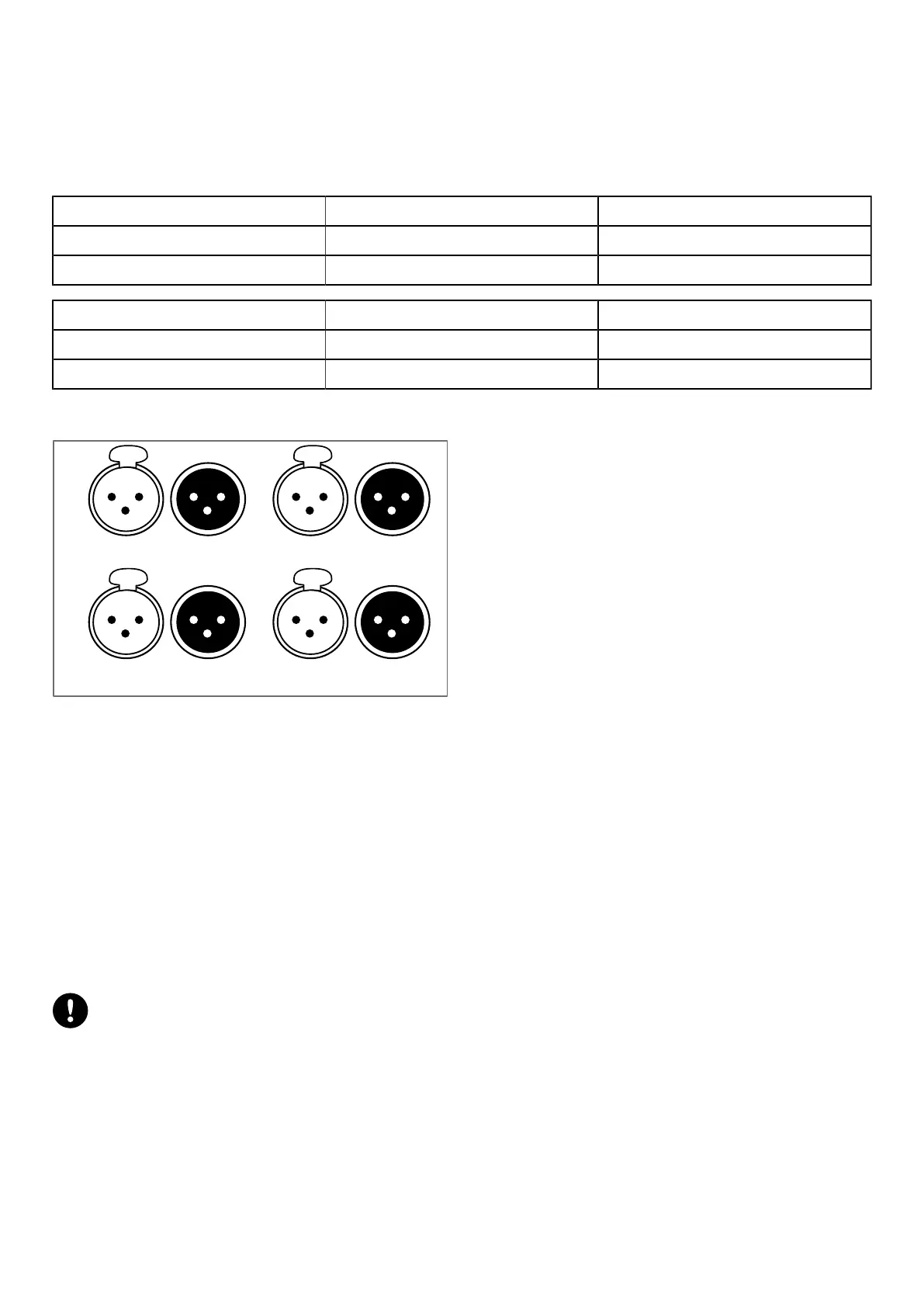
The eight XLR connectors on the rear panel are for analog or digital signal cabling.
The XLR connectors can transport analog or digital signals depending on the input mode selected by the user for channel
pairs AB and CD (the two selections can be different). Connections to the IN connectors are referenced in the table. Refer
also to section XLR INPUT MODE (p.44).
input mode AB IN A / IN A&B IN B
Analog analog audio source (1 channel) analog audio source (1 channel)
AES/EBU digital audio source (2 channels) not used
input mode CD IN C / IN C&D IN D
Analog analog audio source (1 channel) analog audio source (1 channel)
AES/EBU digital audio source (2 channels) not used
Each LINK connector is wired to the corresponding IN connector, and thus transports the same type of signal.
AES/EBU IN A&B
ANALOG IN A
AES/EBU IN C&D
ANALOG IN C
LINK A&B
LINK A
LINK C&D
LINK C
ANALOG IN B
ANALOG IN D
LINK B
LINK D
Analog input mode
The XLR connectors are wired according to IEC 60268-12:
• pin 1: shield
• pin 2: + signal
• pin 3: - signal
The female XLR input connectors ANALOG IN A to ANALOG IN D can receive up to four analog signals (when setting
the analog input mode for channel pairs AB and CD). The headroom of the input circuits is high enough to accept the
maximum output level from virtually any line level signal source (up to 22 dBu).
Each LINK connector is passively wired in parallel to the corresponding IN channel. The input impedance is high enough
(22 kΩ, balanced) to allow multiple parallel input connections.
AES/EBU input mode
Digital audio source specications
Standard: AES/EBU (AES3) or electrical S/PDIF (IEC 60958 Type II)
Sampling frequency: 44.1, 48, 64, 88.2, 96, 128, 176.4 or 192 kHz
Word length: 16, 18, 20 or 24 bits
The AES/EBU inputs are transformer balanced and their XLR connectors are wired according to IEC 60268-12.
The female XLR input connectors AES/EBU IN A&B and AES/EBU IN C&D can receive up to four digital signals (when
setting the AES/EBU input mode for channel pairs AB and CD). The input format is AES/EBU (AES3) or electrical S/PDIF
(IEC 60958 Type II).
Each LINK connector is electronically buffered to allow daisy-chaining any number of amplied controllers. It also features
a failsafe relay to ensure wiring continuity in case of amplied controller shutdown.
LA4X owner's manual (EN) version 14.1 23
 Loading...


