M
Meghan LynchAug 9, 2025
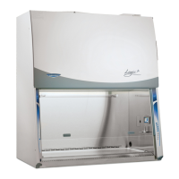
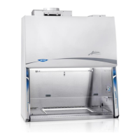
What to do if the Labconco Purifier Logic+ 30241 cabinet blower and lights won’t turn on?
- JJorge RussoAug 10, 2025
If the cabinet blower and lights aren’t working, first, ensure the unit is plugged into the appropriate electrical outlet. Then, check if the System Reset Switch is turned on. Also, reset the circuit breakers. If problems persist, run keypad diagnostics and check connections and raise the sash.