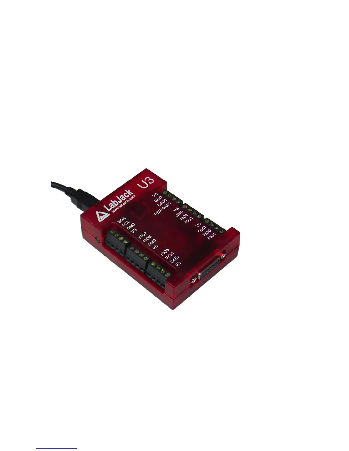
2. Hardware Description
The U3 has 3 different I/O areas:
• Communication Edge,
• Screw Terminal Edge,
• DB Edge.
The communication edge has a USB type B connector (with black cable connected in Figure 2-
1). All power and communication is handled by the USB interface.
The screw terminal edge has convenient connections for the analog outputs and 8 flexible I/O
(digital I/O, analog inputs, timers, or counters). The screw terminals are arranged in blocks of 4,
with each block consisting of Vs, GND, and two I/O. There is also a status LED located on the
left edge.
The DB Edge has a D-sub type connectors called DB15 which has the 8 EIO lines and 4 CIO
lines. The EIO lines are flexible like the FIO lines, while the CIO are dedicated digital I/O.
Figure 2-1. LabJack U3
2.1 USB
The U3 has a full-speed USB connection compatible with USB version 1.1 or 2.0. This
connection provides communication and power (Vusb). USB ground is connected to the U3
ground (GND), and USB ground is generally the same as the ground of the PC chassis and AC
mains.
The details of the U3 USB interface are handled by the high level drivers (Windows LabJackUD
DLL), so the following information is really only needed when developing low-level drivers.
12