One good way to handle low-level signals such as thermocouples is the LJTick-InAmp, which is
2-channel instrumentation amplifier module that plugs into the U3 screw-terminals. Go to
a
labjack.com for more information.
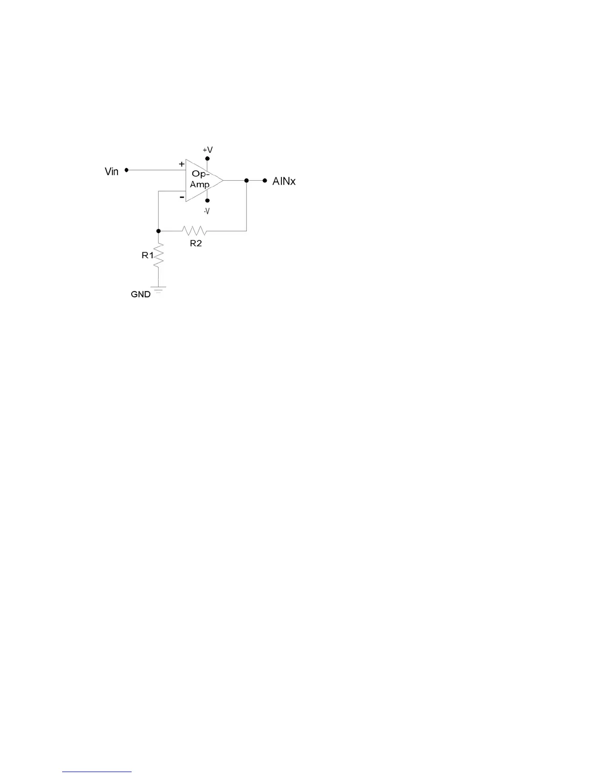
For a do-it-yourself solution, the following figure shows an operational amplifier (op-amp)
configured as non-inverting:
Figure 2-2. Non-Inverting Op-Amp Configuration
The gain of this configuration is:
00 kΩ is a typical value for R2. Note that if R2=0 (short-circuit) and R1=inf (not installed), a
1 is the result.
used to choose an op-amp from the thousands that are available.
ne of the main criteria is that the op-amp can handle the input and output signal range. Often,
e OPA344 from Texas Instruments (ti.com) is
ood for many 5 volt applications.
e
tial signal to single-ended, and generally has a simple
ethod to set gain.
ay to
s is often by using the LJTick-Divider, which is a two channel buffered
ivider module that plugs into the U3 screw-terminals. More information is available at
bjack.com.
Vout = Vin * (1 + (R2/R1))
1
simple buffer with a gain equal to
There are numerous criteria
O
a single-supply rail-to-rail input and output (RIRO) is used as it can be powered from Vs and
GND and pass signals within the range 0-Vs. Th
g
The op-amp is used to amplify (and buffer) a signal that is referred to the same ground as the
LabJack (single-ended). If instead the signal is differential (i.e. there is a positive and negativ
signal both of which are different than ground), an instrumentation amplifier (in-amp) should be
used. An in-amp converts a differen
m
2.6.3.6 Signal voltages beyond 0-2.44 volts (and resistance measurement)
The nominal maximum analog input voltage range for the U3 is 0-2.44 volts. The easiest w
handle larger voltage
d
la
The basic way to handle higher unipolar voltages is with a resistive voltage divider. The
following figure shows the resistive voltage divider assuming that the source voltage (Vin) is
referred to the same ground as the U3 (GND).
20