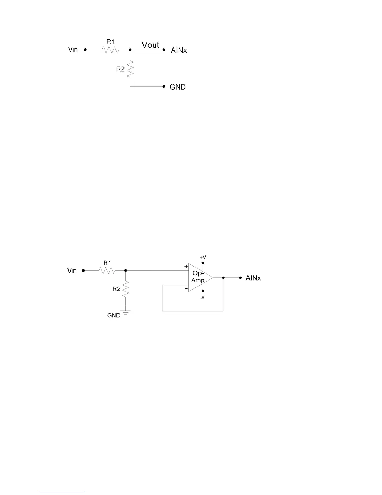
Figure 2-3. Voltage Divider Circuit
The attenuation of this circuit is determined by the equation:
his divider is easily implemented by putting a resistor (R1) in series with the signal wire, and
terminal. To maintain specified
nalog input performance, R1 should not exceed 10 kΩ, so R1 can generally be fixed at 10 kΩ
e desired attenuation. For instance, R2 = 9.1 kΩ provides a
ivide by 2.1, so a ~0-5 volt input will be scaled to the input range of the U3.
The
gured as non-
verting unity-gain (i.e. a buffer).
Vout = Vin * ( R2 / (R1+R2))
T
placing a second resistor (R2) from the AIN terminal to a GND
a
and R2 can be adjusted for th
d
The divide by 2 configuration where R1 = R2 = 10 kΩ, presents a 20 kΩ load to the source,
meaning that a 5 volt signal will have to be able to source/sink up to
+250 µA. Some signal
sources might require a load with higher resistance, in which case a buffer should be used.
following figure shows a resistive voltage divider followed by an op-amp confi
in
Figure 2-4. Buffered Voltage Divider Circuit
The op-amp is chosen to have low input bias currents so that large resistors can be used in the
voltage divider. For 0-5 volt applications, where the amp will be powered from Vs and GND, a
as Instruments (ti.com). The OPA344 has a very
the entire voltage range. Note that when powering
e amp from Vs and GND, the input and output to the op-amp is limited to that range, so if Vs is
nown resistance.
good choice would be the OPA344 from Tex
small bias current that changes little across
th
4.8 volts your signal range will be 0-4.8 volts.
The information above also applies to resistance measurement. A common way to measure
resistance is to build a voltage divider as shown in Figure 2-4, where one of the resistors is
known and the other is the unknown. If Vin is known and Vout is measured, the voltage divider
equation can be rearranged to solve for the unk
21