when the switch is closed. 1 kΩ limits the maximum current to about 5 mA, but better results
might be obtained with smaller resistor values.
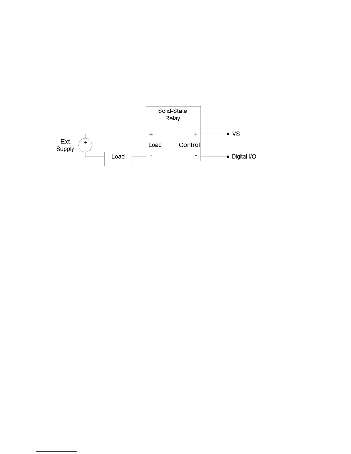
2.8.1.4 Output: Controlling Relays
All the digital I/O lines have series resistance that restricts the amount of current they can s
or source, but solid-state relays (SSRs) can usually be controlled directly by the digital I/O. The
SSR is connected as shown in the following diagram, where VS (~5 volts) connects to the
positive control input and the digital I/O line con
ink
nects to the negative control input (sinking
onfiguration).
c
Figure 2-12. Relay Connections (Sinking Control, High-Side Load Switching)
When the digital line is set to output-low, control current flows and the relay turns on. When the
digital line is set to input, control current does not flow and the relay turns off. When the digital
line is set to output-high, some current flows, but whether the relay is on or off depends on the
specifications of a particular relay. It is recommended to only use output-low and input.
or example, the Series 1 (D12/D24) or Series T (TD12/TD24) relays from Crydom specify a
resulting voltage across the control inputs of the relay will be about 5*1500/(1500+180) =
5*1500/(1500+550) = 3.7 volts (the other 1.3 volts are dropped across the internal
• 0
close to
ss the
00+550) = 1.2 volts. Both of these in the 1.0-3.0 volt region that is not
defined for these example relays, so the resulting state is unknown.
F
max turn-on of 3.0 volts, a min turn-off of 1.0 volts, and a nominal input impedance of 1500 Ω.
• When the digital line is set to output-low, it is the equivalent of a ground connection with
180 Ω (EIO/CIO) or 550 Ω (FIO) in series. When using an EIO/CIO/MIO line, the
4.5 volts (the other 0.5 volts is dropped across the internal resistance of the EIO/CIO
line). With an FIO line the voltage across the inputs of the relay will be about
resistance of the FIO line). Both of these are well above the 3.0 volt threshold for the
relay, so it will turn on.
When the digital line is set to input, it is the equivalent of a 3.3 volt connection with 10
kΩ in series. The resulting voltage across the control inputs of the relay will be
zero, as virtually all of the 1.7 volt difference (between VS and 3.3) is dropped acro
internal 100 kΩ resistance. This is well below the 1.0 volt threshold for the relay, so it
will turn off.
• When the digital line is set to output-high, it is the equivalent of a 3.3 volt connection with
180 Ω (EIO/CIO) or 550 Ω (FIO) in series. When using an EIO/CIO line, the resulting
voltage across the control inputs of the relay will be about 1.7*1500/(1500+180) = 1.5
volts. With an FIO line the voltage across the inputs of the relay will be about
1.7*1500/(15
29