2.6.3.7 Measuring current (including 4-20 mA) with a resistive shunt
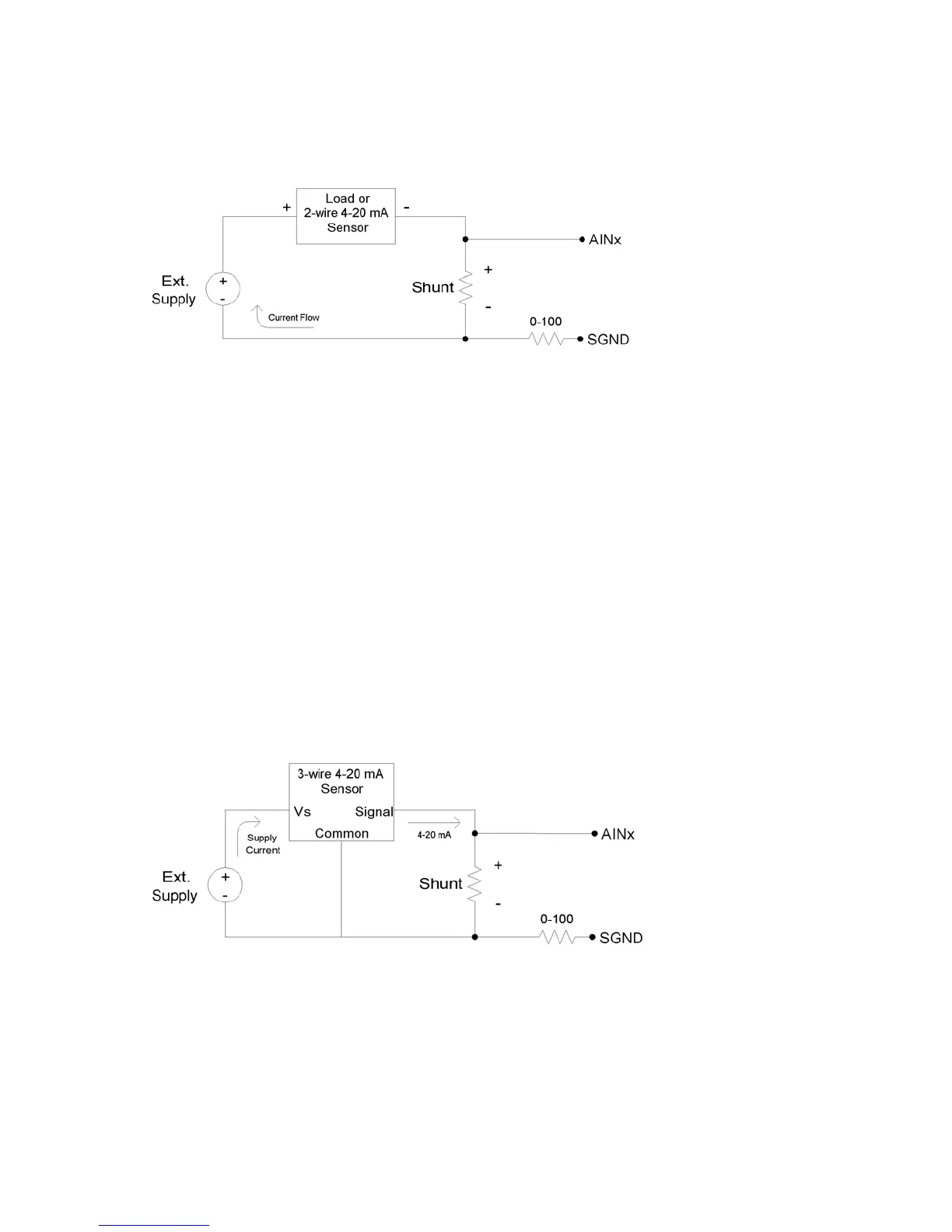
The following figure shows a typical method to measure the current through a load, or to
easure the 4-20 mA signal produced by a 2-wire (loop-powered) current loop sensor. The
urrent shunt shown in the figure is simply a resistor.
m
c
Figure 2-5. Current Measurement With Arbitrary Load or 2-Wire 4-20 mA Sensor
When measuring a 4-20 mA signal, a typical value for the shunt would be 120 Ω. This results in
rovide enough
must provide at
ast 7.4 volts.
0 volts of drop is the most that can be tolerated without affecting the load, a 1.0
resistor could be used. That equates to 1.0 watts, though, which would require a special high
r
a 0.48 to 2.40 volt signal corresponding to 4-20 mA. The external supply must p
voltage for the sensor and the shunt, so if the sensor requires 5 volts the supply
le
For applications besides 4-20 mA, the shunt is chosen based on the maximum current and how
much voltage drop can be tolerated across the shunt. For instance, if the maximum current is
1.0 amp, and 1.
Ω
wattage resistor. A better solution would be to use a 0.1 Ω shunt, and then use an amplifier to
increase the small voltage produced by that shunt. If the maximum current to measure is too
high (e.g. 100 amps), it will be difficult to find a small enough resistor and a hall-effect sensor
should be considered instead of a shunt.
The following figure shows typical connections for a 3-wire 4-20 mA sensor. A typical value fo
the shunt would be 120 Ω which results in 0.48 to 2.40 volts.
Figure 2-6. Current Measurement With 3-Wire 4-20 mA (Sourcing) Sensor
The sensor shown in Figure 2-6 is a sourcing type, where the signal sources the 4-20 mA
current which is then sent through the shunt resistor and sunk into ground. Another type of 3-
the positive supply,
sor ground is
e of
wire sensor is the sinking type, where the 4-20 mA current is sourced from
sent through the shunt resistor, and then sunk into the signal wire. If sen
connected to U3 ground, the sinking type of sensor presents a problem, as at least one sid
the resistor has a high common mode voltage (equal to the positive sensor supply). If the
sensor is isolated, a possible solution is to connect the sensor signal or positive sensor supply
22