power rails). If
±10, ±12, or ±15 volt supplies are available, consider using the LT1490A op-
d
it
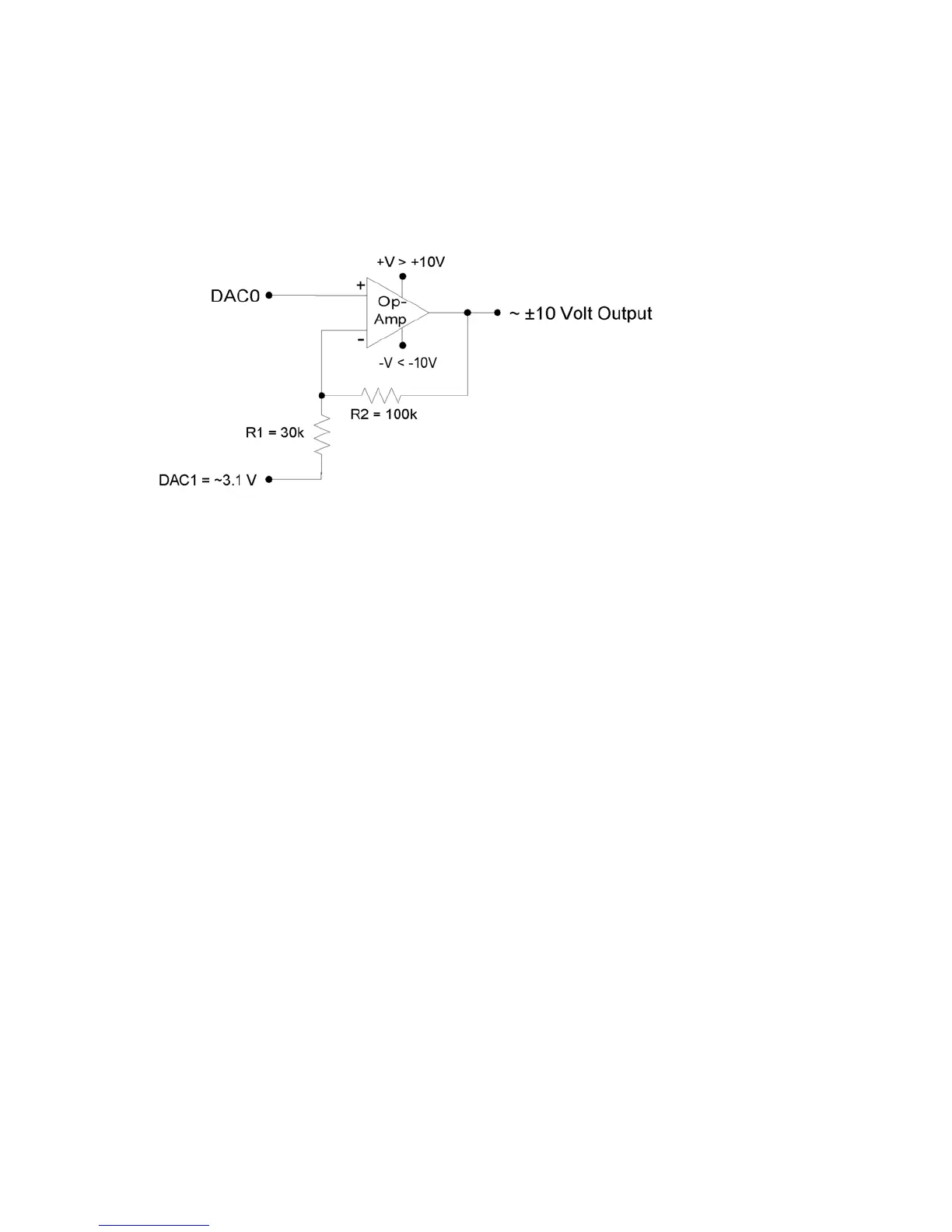
1 can be adjusted to get the
esired gain. A fixed reference (such as 2.5 volts) could also be used instead of DAC1.
amp (linear.com), which can handle a supply span up to 44 volts.
A reference voltage is also required to provide the offset. In the following circuit, DAC1 is use
to provide a reference voltage. The actual value of DAC1 can be adjusted such that the circu
output is 0 volts at the DAC0 mid-scale voltage, and the value of R
d
Figure 2-7. ±10 Volt DAC Output Circuit
A two-point calibration should be done to determine the exact input/output relationship of this
circuit. Ref to application note SLOA097 from ti.com for further information about gain and
IO0-CIO3) are available on the DB15 connector. Each digital line
ured as input, output-high, or output-low. The digital I/O use 3.3 volt
olerant.
-15 EIO0-EIO7
ear on the built-in screw-terminals, while the 8 EIO and 4 CIO lines appear
nnector. See the DB15 Section of this User’s Guide for more information.
ll the digital I/O include an internal series resistor that provides overvoltage/short-circuit
of I/O
tolerant). When configured as output-high, a bit is
onnected to the internal 3.3 volt supply (through a series resistor). When configured as output-
low, a bit is connected to GND (through a series resistor).
er
offset design with op-amps.
2.8 Digital I/O
The LabJack U3 has up to 20 digital I/O channels. 16 are available from the flexible I/O lines,
and 4 dedicated digital I/O (C
can be individually config
logic and are 5 volt t
The LabJackUD driver uses the following bit numbers to specify all the digital lines:
0-7 FIO0-FIO7
8
16-19 CIO0-CIO3
The 8 FIO lines app
only on the DB15 co
A
protection. These series resistors also limit the ability of these lines to sink or source current.
Refer to the specifications in Appendix A.
All digital I/O on the U3 have 3 possible states: input, output-high, or output-low. Each bit
can be configured individually. When configured as an input, a bit has a ~100 kΩ pull-up
resistor to 3.3 volts (all digital I/O are 5 volt
c
25